This post is older than 2 years and might not be relevant anymore
More Info: Consider searching for newer posts

RF Conducted Emissions measurements with nRF52832

Hi,

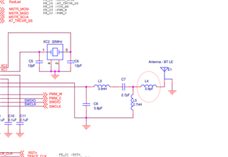
I'd like to inquire about the recommended configuration for RF conducted emissions testing for the BTLE radio on the nRF52832. As in the reference circuit provided in the data sheet, our RF signal flow is as follows:

nRF52832 -> matched network -> 50 ohm antenna

Assuming we remove/disconnect the antenna, does Nordic have a recommended part of this chain where a connection should be made for a regulatory conducted emissions measurement? Should the matched network be removed and the connection made directly to the Nordic or should the matched network be left in place with the connection occurring at the output of the network?

Attached is the relevant portion of our schematic.

Any guidance would be greatly appreciated.

Best,

Eiad Jandali

Parents
  • Note: the assumption we're making here is that the impedance of the connection to board will also be 50 ohms. For that reason it would be useful to know the impedance of the ANT pin on the Nordic - is this information available? The data sheet says the reference circuit (with matching network) are designed for 50 ohm antennas but the impedance of the pin isn't provided.

Reply
  • Note: the assumption we're making here is that the impedance of the connection to board will also be 50 ohms. For that reason it would be useful to know the impedance of the ANT pin on the Nordic - is this information available? The data sheet says the reference circuit (with matching network) are designed for 50 ohm antennas but the impedance of the pin isn't provided.

Children
No Data
Related