This post is older than 2 years and might not be relevant anymore
More Info: Consider searching for newer posts

nRF52832 GPIO incontrollable!

Hi,everybody!

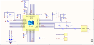
        I use nRF52832,supply volt 3.0V normal,program can be downloaded , run and debug,i ensure the program is accurately.To control a gpio P0.09,on the hardware, P0.09 series a resistor to the led and the led is grounded,in the program I set P0.09 to high level.The led doesn't light up after the program is downloaded,but the bluetooth program normal works.Why? TKS.

Parents
  • Standard output, 0.5mA, taking a look at the spec for that LED it wants more like 20mA, at 0.5mA you're barely turning it on. Even if you could source 20mA from the pin you have a 1K resistor (where did you get THATvalue from). Assuming a Vf on the LED of 2.0v and a supply of 3.0V, your drop over the resistor is 1.0v so your current would be limited to about 1mA even if the pin could supply more. 1mA is so low on the graph of luminous intensity vs current  as to be basically .. off. 

    You can't drive a 20mA nominal current LED from a GPIO, even in High mode  (~5mA) and certainly not  in standard mode (0.5mA) and even if it  could supply 20mA, your current limiting resistor is way too large. I calculate 50 ohms to be closer to the mark. 

  • Thank you for your reply.

    I tested it today,even short-circuited the resistance,there's still no reaction.I measured the gpio high level output voltage only about 0.18v,low level output voltage about 0.00...V. I guess the gpio has no output at all.Don't know why?Is it possible that the chip is broken?

  • Hi RK,

         Before testing again, I removed the LED and the resistance,As you say,I set all P0.09 and P0.10 as output high level, and no external devices were connected at this time. These two pins were suspended. At this time, the output voltage of these two pins should be 3.0v (at this time, the operating voltage of MCU is 3.0v), but after my measurement, it was found that the output voltage of these two pins was around 0.2v or below 0.2v.There is no high level voltage of about 3.0v output at all

  • Hi,RK

        Just now, I suspended the other IO port, wrote the program to enable the IO port to work normally, which can be raised and pulled down.

  • And I set the usable gpio to toggle the high and low level once every 1 second. Then I used the multimeter to see that the gpio is 3.0v for a while and 0v for a while.See the led lights up every once in a while and off every once in a while.

    The above is my description of the phenomenon after the experiment.

  • Although you don't reply, but I also want to say with you, the things settled, is not what we discussed yesterday, is a question of NFC, P0.09 and P0.10 was just what I used as a gpio, it is the default NFC function, so I need to set the register to normal gpio, then everything is normal work, also do not need to add the MOS tube, just change the NFC function to gpio function, can work normally, but still want to thank you.

    const uint32_t UICR_ADDR_0x20C    __attribute__((at(0x1000120C))) __attribute__((used)) = 0xFFFFFFFE;

  • The snippet below is pulled from the SystemInit() function in the system_nrf52.c file , which is run at startup. So if you want to use the NFC pins as GPIOs you simply have to add CONFIG_NFCT_PINS_AS_GPIOS to your preprocessor defines.

      /* Configure NFCT pins as GPIOs if NFCT is not to be used in your code. If CONFIG_NFCT_PINS_AS_GPIOS is not defined,
           two GPIOs (see Product Specification to see which ones) will be reserved for NFC and will not be available as
           normal GPIOs. */
        #if defined (CONFIG_NFCT_PINS_AS_GPIOS)
            if ((NRF_UICR->NFCPINS & UICR_NFCPINS_PROTECT_Msk) == (UICR_NFCPINS_PROTECT_NFC << UICR_NFCPINS_PROTECT_Pos)){
                NRF_NVMC->CONFIG = NVMC_CONFIG_WEN_Wen << NVMC_CONFIG_WEN_Pos;
                while (NRF_NVMC->READY == NVMC_READY_READY_Busy){}
                NRF_UICR->NFCPINS &= ~UICR_NFCPINS_PROTECT_Msk;
                while (NRF_NVMC->READY == NVMC_READY_READY_Busy){}
                NRF_NVMC->CONFIG = NVMC_CONFIG_WEN_Ren << NVMC_CONFIG_WEN_Pos;
                while (NRF_NVMC->READY == NVMC_READY_READY_Busy){}
                NVIC_SystemReset();
            }
        #endif


Reply
  • The snippet below is pulled from the SystemInit() function in the system_nrf52.c file , which is run at startup. So if you want to use the NFC pins as GPIOs you simply have to add CONFIG_NFCT_PINS_AS_GPIOS to your preprocessor defines.

      /* Configure NFCT pins as GPIOs if NFCT is not to be used in your code. If CONFIG_NFCT_PINS_AS_GPIOS is not defined,
           two GPIOs (see Product Specification to see which ones) will be reserved for NFC and will not be available as
           normal GPIOs. */
        #if defined (CONFIG_NFCT_PINS_AS_GPIOS)
            if ((NRF_UICR->NFCPINS & UICR_NFCPINS_PROTECT_Msk) == (UICR_NFCPINS_PROTECT_NFC << UICR_NFCPINS_PROTECT_Pos)){
                NRF_NVMC->CONFIG = NVMC_CONFIG_WEN_Wen << NVMC_CONFIG_WEN_Pos;
                while (NRF_NVMC->READY == NVMC_READY_READY_Busy){}
                NRF_UICR->NFCPINS &= ~UICR_NFCPINS_PROTECT_Msk;
                while (NRF_NVMC->READY == NVMC_READY_READY_Busy){}
                NRF_NVMC->CONFIG = NVMC_CONFIG_WEN_Ren << NVMC_CONFIG_WEN_Pos;
                while (NRF_NVMC->READY == NVMC_READY_READY_Busy){}
                NVIC_SystemReset();
            }
        #endif


Children
No Data
Related