This post is older than 2 years and might not be relevant anymore
More Info: Consider searching for newer posts

Problem Driving MOSFET with GPIO Pin

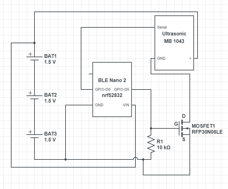
I have a RedBear BLE Nano v2 (nrf52832) connected to 3 AA batteries for power. I also have a Maxbotix (MB1043) ultrasonic sensor attached. I have configured a gpio pin for output and have connected it to an N-Channel MOSFET (RFP30N06LE) to be utilized as a switch. When the GPIO pin is set high, the MOSFET should complete the circuit and turn on the ultrasonic sensor. 

The problem I am having is that the GPIO pin is not causing the MOSFET to complete the circuit. If instead, I supply the MOSFET gate with the battery, it works as expected and turns on the sensor. I measured the voltage and current as exactly the same from the battery as from the GPIO pin. So my question is why is the GPIO pin failing to activate the MOSFET?

Parents Reply
  • can't instantly see anything wrong with that, but can't find the specs of the mosfet to check Vgs on. Don't quite see the point of R1, that's just going to bleed current when the GPIO is on, I'd have a small resistor in series with the gate to stop inrush current but not as a voltage divider. Can't  see it wouldn't work though. 

    You said  you  tested by supplying the gate from the battery, did you give it the full 4.5v from the battery or just the 3v (3.3v) you'd actually get from the GPIO? 

    Just another check question, you are setting the GPIO as output and setting it high, not just using the  pull-up (which would then voltage divide with R1). Didn't seem likely but worth asking. 

Children
No Data
Related