This post is older than 2 years and might not be relevant anymore
More Info: Consider searching for newer posts

SPI Read issue

Hi,

I am using nRF52832 microcontroller in project. 

I use SPI interface for serial EEPROM.

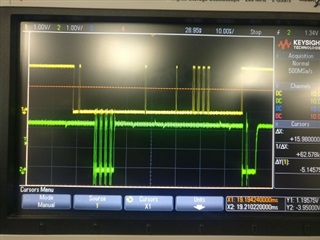
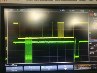
I could able to see write packets are getting transmitted and verified the signals by probing. SS, SCK and MOSI are perfect.

But when i initiate the Read sequence, I could see the clock is transmitting the Read Instruction Code and Followed by from which address the read should start. Verified the same via probing the signal. But slave is not responding i am seeing continuous HIGH state on the MISO line. Application software read the receive buffer content as 0x00 at all time.

So kindly share your suggestions and possible reasons for fixing this issue.

Note: M95M02 is the serial flash part number that i am using.

Thanks & Regards,

Chinnasamy.

Parents
  • Please post the code snippet where you initialize the SPI driver and send the read instruction. It would also be helpful if you could post a logic trace of the SPI lines when you send the read instruction. 

  • Attached the MOSI and MISO signal CRO captures. I could see the write and read data on the SPI lines. But MISO data is not reflecting on the receive buffer.

    Image1

    Image2

    The Yellow line in the above picture is MOSI and Green is MISO.

    Its is a combination of Read(Read Command + Start Address) and Write sequence (Write Enable, Write Command + Start Address, Data)

    Image 1 Data is 0x50

    Image 2 Data is 0x55

    Yellow line (MOSI) Read Command is sent followed by read address ( 24 bit address - 0x00,0x00,0x00). And response for the received command is in green (MISO) line 0x50(image1) and 0x55(image2). Reading 4 bytes of data from starting location 0x00.

    Yellow line (MOSI), Write Enable, Wrtie Command is sent followed by read address ( 24 bit address - 0x00,0x00,0x00) and four byutes of data (0x50 - (Image1), 0x55 (image2), Write status command. Response for the received command is in green (MISO) status byte . 

    Conclusion: Analysing both images, Even if write different data in the location (0x00) during the read sequnce i could see the same data (Data written in wrtie sequence) in the MISO lines but same data i am not able to capture in the receive buffer for the further processing.

    Knidly share your thoughts in the same.

    Thanks & Regards,

    Chinnasamy.

Reply
  • Attached the MOSI and MISO signal CRO captures. I could see the write and read data on the SPI lines. But MISO data is not reflecting on the receive buffer.

    Image1

    Image2

    The Yellow line in the above picture is MOSI and Green is MISO.

    Its is a combination of Read(Read Command + Start Address) and Write sequence (Write Enable, Write Command + Start Address, Data)

    Image 1 Data is 0x50

    Image 2 Data is 0x55

    Yellow line (MOSI) Read Command is sent followed by read address ( 24 bit address - 0x00,0x00,0x00). And response for the received command is in green (MISO) line 0x50(image1) and 0x55(image2). Reading 4 bytes of data from starting location 0x00.

    Yellow line (MOSI), Write Enable, Wrtie Command is sent followed by read address ( 24 bit address - 0x00,0x00,0x00) and four byutes of data (0x50 - (Image1), 0x55 (image2), Write status command. Response for the received command is in green (MISO) status byte . 

    Conclusion: Analysing both images, Even if write different data in the location (0x00) during the read sequnce i could see the same data (Data written in wrtie sequence) in the MISO lines but same data i am not able to capture in the receive buffer for the further processing.

    Knidly share your thoughts in the same.

    Thanks & Regards,

    Chinnasamy.

Children
No Data
Related