This post is older than 2 years and might not be relevant anymore
More Info: Consider searching for newer posts

Getting analog values from different channels using SAADC example

Hello ,

I want to read around 6 analog pins, not necessarily simultaneously. I could afford some delay in between them. i am using nrf52832 dev kit with sdk 15. How do i modify the SAADC example to achieve the same because the example only reads 1 channel. i did found this thread https://devzone.nordicsemi.com/f/nordic-q-a/5561/adc-from-various-pins/19481#19481 which looks similar but i was unable to open the GitHub link provided in the thread. Can you please direct me to the relevant examples. 

Thank you!

Parents
  • Hello,

    It should be fine to measure 6 ADC channels at once.

    Attached is a slightly modified project from the SDK15.0.0\examples\peripheral\saadc example. Only the main.c file is changed. It will measure the 6 pins AIN0 - AIN5, and print the values in the UART log.

    saadc_x_2.zip


    Remember that AIN0 is not the same as A0 printed on the PCB. The AINx pins are:

    AIN0 = P0.02
    AIN1 = P0.03
    AIN2 = P0.04
    AIN3 = P0.05
    AIN4 = P0.28
    AIN5 = P0.29


    Best regards,

    Edvin

  • Hello Edvin, that was a great help. I was wondering what would i have to do to take the readings from the other 2 analog pins? it does not have to be at same time. could be after a delay, but how do i take those readings as well?

    Thanks! 

  • Hello,

    In the SAADC example you can see two functions which sets up and enables the saadc callback:

    saadc_sampling_event_init() and saadc_sampling_event_enable().

    What they do is that they set up a timer and a PPI, and connect the two. This means that the timer interrupt is not called in the application, but when the timeout occurs, the chip will automatically call nrfx_saadc_sample().

    When this function is called N times, where N is the size of your SAADC buffer, that is N = SAMPLES_IN_BUFFER, you will get the callback function.

    I don't know whether you are familiar with the PPI, but it is a module which, when enabled, can perform tasks without involving the CPU. In this case, it works a bit like an advanced timer.


    I really recommend that you use this implementation to trigger the samples. It will not work to call nrfx_saadc_sample() N times in a row in the application, because the sample has to finish before calling nrfx_saadc_sample again.


    Regarding the conversion from the raw SAADC value to voltage, there are a few things to take into consideration:

    Your resolution (by default set to 10 bits, your gain, usually set to 1/6. 

    Please see this scheeme:

    http://infocenter.nordicsemi.com/index.jsp?topic=%2Fcom.nordic.infocenter.nrf52832.ps.v1.1%2Fsaadc.html&anchor=saadc_overview


    From the link: 

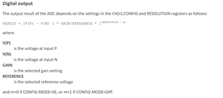
    RESULT = [V(P) – V(N) ] * GAIN/REFERENCE * 2(RESOLUTION - m)

    Which means that V(P) - V(N) = RESULT/ (GAIN/REFERENCE * 2(RESOLUTION - m))


    The result is linear, so you can also do some measurements to known voltages (using a voltmeter), and map the result to voltage using this.


    Best regards,
    Edvin


  • Hello Edvin, 

    V(p) : voltage at input p 

    V(n): voltage at input n, I do not exactly understand this. What are N and P? reference voltage and input voltage? 

    Thanks and Regards,

    Arshdeep

  • This is the positive and negative inputs. I don't know exactly where you found this, but it is possible to use a different reference voltage than GND. The default setup is to use pin_n as ground (NRF_SAADC_INPUT_DISABLE).


    If you want to measure the voltage between two pins, where none of them are GND, you can use pin_n = another pin, and the result will be the difference between the pins.


    Best regards,

    Edvin

  • Hello Edvin,

    I was referring this post in the datasheet. In my case I only want to measure the voltage from the interfaced sensor on the analog pins. So using this formulae: my Vp would be the voltage on the pin from the sensors and Vn would be 0 if I use reference voltage as 0? does it sound right?

  • Yes. That is correct. If you set Vn = NRF_SAADC_INPUT_DISABLE (the default setting) it will measure the voltage difference between GND (0) and Vp.


    Best regards,

    Edvin

Reply Children
Related