This post is older than 2 years and might not be relevant anymore
More Info: Consider searching for newer posts

How to set the PIN 9 with 3.3v as output in nrf52810 ?

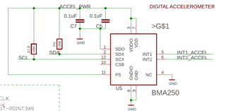
I am working on a custom board based on nrf52810 that my client provided. In this board the accelerometer (Bosch BMA250E) power has been controlled by the PIN 9. However when i try to set the pin for gpio output in code i am getting only 0.6 volts as output. But my accelerometer needs 3.3 volts to power up and running (as low as 2.6 volts is good). In the nrf52810 Datasheet there is nothing mentioned about this. I own a nrf52DK which has nrf52832. In the nrf52832 Datasheet it has been mentioned these pins are NFC and GPIO multipurpose pins and they have limitations in used as GPIO pins which also seems like my problem. We searched the devzone and found this thread https://devzone.nordicsemi.com/f/nordic-q-a/29041/how-to-enable-p0-09-and-p0-10-as-gpio-pins-on-the-nrf52-instead-of-nfc-pins and tried all the steps. But still i cannot get high enough voltage to operate the accelerometer.

  • Hello,

    Have you tried any of the other pins, just to see if this is related to the NFC pins or not?

    Do you know how much current your sensor is drawing? The more current it draws, the lower the output voltage will be, due to the internal resistors on the pins.

    Have you tried to set the pin in High Drive? See this link.

    Setting the pin in high drive reduces the internal resistor, allowing to provide more current. If you need even more, you can set up to 3 pins in high drive, and provide 15mA. But I don't know if your PCB allows this, or how much current your sensor draws.


    But have you tested on another pin (not P0.09 or P0.10), to see whether this is an NFC-pin related issue or a current related issue?


    Best regards,

    Edvin


  • In the nrf52 DK i tried with different PIns 25,24 and 6 with the accelerometer's dev board (shuttle board). And it worked. When i measured the output volts from these pins i got 2.8 to 3.3 volts and the TWI_Scanner sdk 15 example found my accelerometer I2C address 0x18 correctly. That's how i figured out the NFC pins problem. However in the Custom board this pin 9 is soldered to the accelerometer power so i couldn't disconnect it. But even weird happened when i shorted another free GPIO pin 20 with this pin 9 with necessary code changes. When i measure the P20 individually it shows 2.8 volts, but after shorting pin 20 with pin 9 physically with wires, the voltage goes down to 0.65 volts. 

  • Have you checked the NFCPINS register in the UICR to be sure it's set with the least significant bit as zero? That is the best way to ensure that you HAVE actually set it into GPIO mode. If you haven't then go back and work out why setting the define hasn't worked for you. Just put a breakpoint at the start of main, then use your debugger to get the value in address 0x1000120C. 

    Your issue sounds like the pin is still in NFC mode. So do that test first before shorting pins together. 

  • As mentioned, there is an internal resistor. If the sensor draws a lot of current, the voltage will go down (because the voltage on the internal resistor increases with higher current).

    The reason I asked you to try another pin than the NFC pin is because there is something special with the NFC pins. There is a protection circuit that shorts the pins together if they are driven too far apart. But I forgot that the nRF52810 doesn't have NFC, so that shouldn't be an issue.


    I looked at the datasheet for your sensor. It is this one, right?

    It should only draw 130µA, so it should be fine, even without high drive. 

    When you tested with pin 20. Was pin 9 set to output or input then? If it is not initialized, it is set to input by default, so it shouldn't draw the pin in any direction?


    It sounds like there might be some soldering issues on your PCB, or an issue with the PCB layout itself. Are you sure that you have attached it to the correct pin on the sensor?

    Somehow the pin is connected to GND. Either through a bad solder, or through some component that is attached incorrect. But can you first check that you are connecting to the correct pin on the sensor, and then go over the solders, to see that it is not connected to GND?


    Best Regards,

    Edvin


  • Thanks Edvin i am aware of the protection circuit and current leakage between pin 9 and 10 in the nrf52832 DK and the nrf52810 doesn't have the NFC peripherals. That's why i mentioned in the question that it was similar to my problem. When i shorted the pins 20 and 9 , the pin9 was not initialized. However i am sure it is not a soldering issue as i have 2 of the same custom boards and both the boards behave same. The accelerometer power is connected to the pin 9 as in the following image as mentioned in the accelerometer's datasheet. The PCB schematics i have is clear. Let me check the physical layout and update. In the mean time if you have any more ideas on this issue, like brain-storming, let me know and i will check and update you.


Related