
Hello everybody,
I ran into an unpleasant moment: sometimes the timer counts incorrectly in the counter mode.
What is used:
- Custom board with BC832 (Fanstel, NRF52832xxAA);
- SDK v15.0.0. SD 6.1.0;
- Segger Embedded Studio;
Additional components:
- ADS1292 (SPI);
- two I2C devices (charger and accelerometr);
What should be done:
- Read data from ADS (1 kHz) and read data from i2c devices (~100 Hz);
- Generate a square wave at a frequency of 25 Hz based on the data ready signal from the ADS1292;
The following settings have been used for the operation of the SPI:
void AdsInitHW (void)
{
  // Настройка входа готовности данных
  NRF_GPIO->PIN_CNF[AFE_DRDYn] = 0x00;
  NRF_GPIO->PIN_CNF[AFE_DRDYn] = (GPIO_PIN_CNF_DIR_Input << GPIO_PIN_CNF_DIR_Pos) | (GPIO_PIN_CNF_PULL_Disabled << GPIO_PIN_CNF_PULL_Pos);

  // ADS Dready
  NRF_GPIOTE->CONFIG[AFE_DRDY_GPIOTE] |= GPIOTE_CONFIG_MODE_Event << GPIOTE_CONFIG_MODE_Pos;
  NRF_GPIOTE->CONFIG[AFE_DRDY_GPIOTE] |= AFE_DRDYn<<GPIOTE_CONFIG_PSEL_Pos;
  NRF_GPIOTE->CONFIG[AFE_DRDY_GPIOTE] |= GPIOTE_CONFIG_POLARITY_HiToLo << GPIOTE_CONFIG_POLARITY_Pos;

  // (Chip Select)
  NRF_GPIOTE->CONFIG[AFE_CS_GPIOTE] |= GPIOTE_CONFIG_MODE_Task << GPIOTE_CONFIG_MODE_Pos;
  NRF_GPIOTE->CONFIG[AFE_CS_GPIOTE] |= AFE_CSn<<GPIOTE_CONFIG_PSEL_Pos;
  NRF_GPIOTE->TASKS_SET[AFE_CS_GPIOTE] = 1; // ChipSelect not active

  NRF_PPI->CH[AFE_PPI_Ch2].EEP	= (uint32_t) &AFE_SPI->EVENTS_ENDTX;
  NRF_PPI->CH[AFE_PPI_Ch2].TEP	= (uint32_t) &NRF_GPIOTE->TASKS_SET[AFE_CS_GPIOTE];


  AFE_SPI->ENABLE	= SPIM_ENABLE_ENABLE_Enabled;

  AFE_SPI->PSEL.SCK   = ((AFE_SCLK<<SPIM_PSEL_SCK_PIN_Pos)	| (SPIM_PSEL_SCK_CONNECT_Connected  << SPIM_PSEL_SCK_CONNECT_Pos));
  AFE_SPI->PSEL.MISO	= ((AFE_DOUT<<SPIM_PSEL_MISO_PIN_Pos)	| (SPIM_PSEL_MISO_CONNECT_Connected << SPIM_PSEL_MISO_CONNECT_Pos));
  AFE_SPI->PSEL.MOSI	= ((AFE_DIN<<SPIM_PSEL_MOSI_PIN_Pos)	| (SPIM_PSEL_MOSI_CONNECT_Connected << SPIM_PSEL_MOSI_CONNECT_Pos));
  AFE_SPI->CONFIG     = SPIM_CONFIG_CPHA_Trailing<<SPIM_CONFIG_CPHA_Pos;
  AFE_SPI->FREQUENCY	= SPIM_FREQUENCY_FREQUENCY_K250;

  AFE_SPI->INTENSET = SPIM_INTENSET_STOPPED_Set << SPIM_INTENSET_STOPPED_Pos;
  AFE_SPI->INTENSET = SPIM_INTENSET_ENDRX_Set   << SPIM_INTENSET_ENDRX_Pos;
  AFE_SPI->INTENSET = SPIM_INTENSET_END_Set     << SPIM_INTENSET_END_Pos;
  AFE_SPI->INTENSET = SPIM_INTENSET_ENDTX_Set   << SPIM_INTENSET_ENDTX_Pos;
  AFE_SPI->INTENSET = SPIM_INTENSET_STARTED_Set << SPIM_INTENSET_STARTED_Pos;

  NVIC_EnableIRQ(AFE_IRQ);
}

void AdsSetFrameConfig (uint8_t sample_size, uint8_t frame_size, uint8_t frame_sync, uint8_t *data_ptr)
{

  NRF_PPI->CH[AFE_PPI_Ch1].EEP	= (uint32_t) &NRF_GPIOTE->EVENTS_IN[AFE_DRDY_GPIOTE];
  NRF_PPI->CH[AFE_PPI_Ch1].TEP	= (uint32_t) &NRF_GPIOTE->TASKS_CLR[AFE_CS_GPIOTE];
  NRF_PPI->FORK[AFE_PPI_Ch1].TEP= (uint32_t) &AFE_SPI->TASKS_START;

  NRF_PPI->CH[AFE_PPI_Ch2].EEP	= (uint32_t) &AFE_SPI->EVENTS_ENDRX;
  NRF_PPI->FORK[AFE_PPI_Ch2].TEP= (uint32_t) &AFE_EV_CNT->TASKS_COUNT;

  NRF_PPI->CHENSET = 1 << AFE_PPI_Ch1;
  NRF_PPI->CHENSET = 1 << AFE_PPI_Ch2;

  AFE_SPI->RXD.LIST   = SPIM_RXD_LIST_LIST_ArrayList;
  AFE_SPI->RXD.PTR    = (uint32_t)data_ptr;
  AFE_SPI->RXD.MAXCNT = sample_size;

  AFE_SPI->TXD.PTR    = NULL;
  AFE_SPI->TXD.MAXCNT = 0;

  AFE_EV_CNT->MODE    = TIMER_MODE_MODE_LowPowerCounter<<TIMER_MODE_MODE_Pos;
  AFE_EV_CNT->BITMODE = TIMER_BITMODE_BITMODE_08Bit;
  AFE_EV_CNT->CC[0]   = frame_size; // 1 frame = 100 samples
  AFE_EV_CNT->CC[1]   = frame_sync; // for sync run another stream
  AFE_EV_CNT->SHORTS  = TIMER_SHORTS_COMPARE0_CLEAR_Enabled << TIMER_SHORTS_COMPARE0_CLEAR_Pos;

  AFE_EV_CNT->INTENSET = TIMER_INTENSET_COMPARE0_Enabled << TIMER_INTENSET_COMPARE0_Pos;
  AFE_EV_CNT->INTENSET = TIMER_INTENSET_COMPARE1_Enabled << TIMER_INTENSET_COMPARE0_Pos;
  NVIC_SetPriority(AFE_EV_CNT_IRQ, AFE_EV_CNT_IRQ_PR);
  NVIC_EnableIRQ(AFE_EV_CNT_IRQ);
  AFE_SPI->EVENTS_END = 0;
  AFE_EV_CNT->TASKS_START = 1;
}

void ZondFreqHwInit(void)
{
  F_SKIN_TIMER->MODE    = TIMER_MODE_MODE_Counter<<TIMER_MODE_MODE_Pos;
  F_SKIN_TIMER->BITMODE = TIMER_BITMODE_BITMODE_08Bit;
  F_SKIN_TIMER->CC[0]   = (1000/25)/2; //  25 Hz

  NRF_GPIOTE->CONFIG[F_SKIN_GPIOTE] |= GPIOTE_CONFIG_MODE_Task << GPIOTE_CONFIG_MODE_Pos;
  NRF_GPIOTE->CONFIG[F_SKIN_GPIOTE] |= GPIOTE_CONFIG_POLARITY_Toggle<<GPIOTE_CONFIG_POLARITY_Pos;
  NRF_GPIOTE->CONFIG[F_SKIN_GPIOTE] |= F_SKIN<<GPIOTE_CONFIG_PSEL_Pos;


  NRF_PPI->CH[F_SKIN_PPI_CH1].EEP	= (uint32_t) &NRF_GPIOTE->EVENTS_IN[AFE_DRDY_GPIOTE];
  NRF_PPI->CH[F_SKIN_PPI_CH1].TEP	= (uint32_t) &F_SKIN_TIMER->TASKS_COUNT;

  NRF_PPI->CH[F_SKIN_PPI_CH2].EEP 	= (uint32_t) &F_SKIN_TIMER->EVENTS_COMPARE[0];
  NRF_PPI->CH[F_SKIN_PPI_CH2].TEP 	= (uint32_t) &NRF_GPIOTE->TASKS_OUT[F_SKIN_GPIOTE];
  NRF_PPI->FORK[F_SKIN_PPI_CH2].TEP = (uint32_t) &F_SKIN_TIMER->TASKS_CLEAR;

  NRF_PPI->CHENSET = 1 << F_SKIN_PPI_CH1;
  NRF_PPI->CHENSET = 1 << F_SKIN_PPI_CH2;
}
Function AdsInitHW () is used at start to adjust the part.
The function AdsSetFrameConfig () is used after the program setting of the ADC to set the counting timer for the received data. On the ready data signal, the PPI lowers the CS signal and starts reading the data. Upon completion of the reading, the PPI raises the CS and increments the counter. When 100 is reached, an interrupt is called, in which the data is transferred to the handler (FreeRTOS stream) and switches the buffer to the DMA ArrayList.
The function ZondFreqHwInit() is used to configure a rectangular waveform generator. By the event of readiness of data from the ADC, the counter is incremented. When the value 20 is reached, the output state is inverted and the timer is reset.
Everything works as intended, but ...
Logical analyzer recording showed a situation when the output inversion occurs not on the 20th event, but on the 19 (!). This behavior is repeated, but in a completely random way.
I attach the screenshots of the logical analyzer recording.
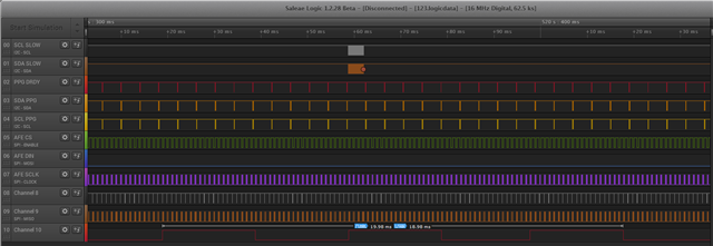
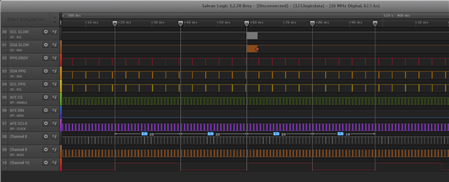
The screenshot shows that for some reason there was a reaction to 19 pulses. At the same time, the other systems work normally.
I can not understand with what it can be connected.

