This post is older than 2 years and might not be relevant anymore
More Info: Consider searching for newer posts

nRF24L01P continuous transmitting inspect

Hi,

I am working on a project with nRF24L01P. Recently I was trying to make nRF24L01P to transmit packet continuously and i have configure the chip in no_ack, TX and  shockburst mode after chip powers on .RF data rate is 1 Mbps and the W_TX_PL_NO_ACK command is used for writing data into tx fifo.How I can know that nRF24L01P does work as I desired.

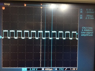
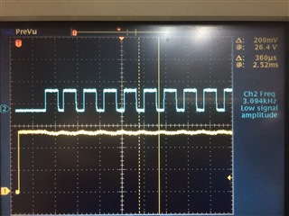
My current code flow is writing data into tx fifo first, shifting CE,querying TX_FULL bit in the STATUS register, if it is low,the MCU will write identical data into tx fifo until quantity of the packet  equals up-limit I specified. All previous action described in code flow is done in a while loop. There is a oscilloscope by hand and I have tested the VDD_PA signal using it. It is shown that the signal VDD_PA has obviously a 360-us period.Is that right ?

Parents
  • Hello,

    It seems correct, but can you share the VDD_PA screenshot by the oscilloscope? 

    Best regards,
    Kenneth

  • Hi,

    Kenneth.This is the screenshot of VDD_PA waveform. Two vertical bars define a period. However, the period of VDD_PA varise at the beginning of VDD_PA asserted or at every 15, 16 or 17 waveform. Is one waveform denote one transmission? I have count the waveform and surprisingly found that the number is not equal to the total number of writing data into the tx fifo. Currently the data written into tx fifo every time is just 1 byte and the speed of SPI is 1 Mbps. TX address is 5-byte long and 1-byte CRC is set for data correction.

    Best regards,

    jinss

  • Hi,

    There is something not entirely correct here. The PLL settling time for transmission is about 130us, during this period VDD_PA will be low about 80us, and high 50us. The transmission itself is about 1us for each bit, e.g. preamble+address+pid+payload+crc, likely 10+40+8+8+8=74us. What is the timing of CE compared to VDD_PA here? Can you show CE in the trace?

    Best regards,
    Kenneth

  • Hi,

    Kenneth. I forgot to told you that the nRF24L01P has a PA connected to. According to the nRF24L01P datasheet,I think the chip in shockburst  mode does not include PID in RF packet and preamble is 8-bit long.I think that the total packet length is 56 bits. There is about 512 us between CE goes high and VDD_PA asserts and VDD_PA  holds low level during toggling for about 144 us as I measured on oscilloscope. 

    Best regards,

    jinss

  • I think the case here is that some of the packets are sent back-to-back, where the radio does not transition to idle state between packet transmissions. So when VDD_PA is high here it likely is transmitting ((360us-150us)/~55us) = 4packets in a row. If you only toggle CE high for 10us I believe you should get more consistent behaviour. Can that make sense?

    Best regards,
    Kenneth


Reply
  • I think the case here is that some of the packets are sent back-to-back, where the radio does not transition to idle state between packet transmissions. So when VDD_PA is high here it likely is transmitting ((360us-150us)/~55us) = 4packets in a row. If you only toggle CE high for 10us I believe you should get more consistent behaviour. Can that make sense?

    Best regards,
    Kenneth


Children
No Data
Related