This post is older than 2 years and might not be relevant anymore
More Info: Consider searching for newer posts

HW UART Configuration for the Radio Test Example

Hi,

I have recently tested some commands from the radio test example given in the following link using a PredevKit for the nRF52840 and it was quite fine:

http://infocenter.nordicsemi.com/index.jsp?topic=%2Fcom.nordic.infocenter.sdk5.v15.0.0%2Fnrf_radio_test_example.html&cp=4_0_0_4_5_29

During that process, I got to know that a UART connection is required. What I have accounted for on the custom board are only the SWD lines as the only way to talk to the BTIC.

However that's not a big deal, since I am preparing for the next revision of the custom design.

I would like thereafter to have the option of using the radio test in that.

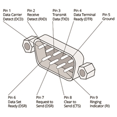
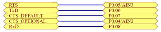
Therefore could you please confirm the following pins from the BTIC that are needed?

Are the CTS and RTS mandatory if the connection is to be made to a PC through an adapter? Recommendation for an adapter please.

Or can one use the Dev Kit for connecting to the uart of the custom board? What pins are then required?

Also I would drop the CTS_OPTIONAL. Please confirm.

Please note I am searching for the configuration that gives me the least amount of BTIC pins that need to be reserved. Thanks

  • You need RXD, TXD and GND, the pins are fully configurable (you can use any GPIO pins). To interface from a PC you can for instance use a FTDI USB to UART (e.g. 3.3V TTL) bridge.

    Best regards,
    Kenneth

  • Hi, I've flashed the Radio Test example onto the custom board, connected the UART interface of the custom board to the predevelopment kit (same pinning for both) and checked the radio example using the PC connected to the predevelopment kit. It worked. In fact both were running at the same time. I knew that the custom board is responding to the radio test since the power for the TX sweep on the spectrum analyzer is clearly higher when both are connected. On the SA I am having antenna.

    So, custom board responding to the Radio mode confirmed! (Even with only RxD and GND connected, it still worked).

    Now I am taking an off the shelf bridge adapter, connecting the GND, TxD and RxD to the custom board (P0.06 and P0.08 for TX and RX respectively), and using putty trying to send the commands as before. Not working!

    Please assist.

    Below the pinning of the serial adapter I am using:

  • Have you confirmed voltage is 3.3V on for instance TXD? And VDD on board is the same?

    Can you see any activity on a logic analyzer trace?

    Best regards,
    Kenneth

Related