
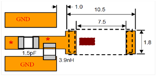
Hi I am working on pcb design for a long range application with nRF52832. There are lc circuit which is implemented to antenna pins on reference design of nrf52832. I decided to use chip antenna which is from johanson technologys' model number 2450AT45A100E. The company, owner of these antenna suggest to use different lc design to get best results. Should I remove the lc circuit from circuit to add chip antennas' layout application. I am sending pcb circuits screenshots. Also Have you got any suggestion like using amplifier IC to improve antenna design and communication quality.
Thanks a lot..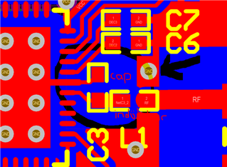
King Regards.
