This post is older than 2 years and might not be relevant anymore
More Info: Consider searching for newer posts

Measuring RTT & RSSI through Radio States

Hi everyone, for the project I'm developing it's extremely important to measure RTT as accurately as possible and as such, after some SoftDevice specification I imagined the following scenario:

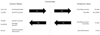
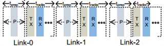
Both devices would be connected and through the connection events packets that are exchanged periodically, I would generate interrupts from the SoftDevice upon reaching three specific states. Now, these interrupts would merely start / stop counters, hopefully, not ruining radio synchronization.

For the init the code is:

#define RADIO_IRQN_PRIORITY	        APP_IRQ_PRIORITY_LOW		/**< Radio Interrupt Request priority. */

// Timer Evt_handler is required not to be NULL, so here it is, a full fledge, state of the art event handler.
void ble_pds_counter_evt_handler(nrf_timer_event_t event_type, void * p_context)
{
    return;
}


/**@brief Function for the Timer initialization.
 *
 * @details Initializes the timer module.
 *
 */
static void timers_init(void)
{
    ret_code_t err_code = app_timer_init();
    APP_ERROR_CHECK(err_code);
    
    nrf_drv_timer_config_t counter_cfg = NRF_DRV_TIMER_DEFAULT_CONFIG; 
    err_code = nrf_drv_timer_init(&delay_counter,  &counter_cfg, ble_pds_counter_evt_handler);
    APP_ERROR_CHECK(err_code);
}

/**@brief Function for initializing the radio interrupts needed.
 */
static uint32_t ble_radio_notif_init(void)
{
    ret_code_t err_code;
    
    NRF_RADIO->INTENSET =   RADIO_INTENSET_ADDRESS_Enabled  << RADIO_INTENSET_ADDRESS_Pos   |
	            RADIO_INTENSET_DEVMATCH_Enabled << RADIO_INTENSET_DEVMATCH_Pos  |
	            RADIO_INTENCLR_CRCOK_Enabled    << RADIO_INTENCLR_CRCOK_Pos     |
	            RADIO_INTENCLR_DISABLED_Enabled << RADIO_INTENCLR_DISABLED_Pos;
	            
    
    // Initialize Radio Notification software interrupt
    err_code = sd_nvic_ClearPendingIRQ(RADIO_IRQn);
    APP_ERROR_CHECK(err_code);
    
    APP_IRQ_PRIORITY_LOW;
        
    err_code = sd_nvic_SetPriority(RADIO_IRQn, RADIO_IRQN_PRIORITY);
    APP_ERROR_CHECK(err_code);
        
    err_code = sd_nvic_EnableIRQ(RADIO_IRQn);
    APP_ERROR_CHECK(err_code);
        
    // Configure the event - ONLY SHOWS ON/OFF ?
    //return sd_radio_notification_cfg_set(NRF_RADIO_NOTIFICATION_TYPE_INT_ON_BOTH, distance);    
}

/**@brief Function for application main entry.
 */
int main(void)
{
    (...)
    ble_radio_notif_init();
    ble_stack_init();
    swi_init();
    (...)
    
    for (;;)
    {
        idle_state_handle();
    }
}

And the radio notification event handler (SWI is used to process both reading and notify central) :

void RADIO_IRQHandler(void)
{
    if (m_pds.state != 0 || m_pds.state == 4)
    {
        if   (NRF_RADIO->EVENTS_DEVMATCH &&
             m_pds.state == 1)
        {
            // Rx   DEVICE MATCH
            nrf_drv_timer_enable(&delay_counter);
            m_pds.state = 2;
        }  else if  (NRF_RADIO->EVENTS_CRCOK &&
	    m_pds.state == 2)
        {
            // Rx   CRC OK
            m_pds.state = 3;
            
        } else if  (NRF_RADIO->EVENTS_ADDRESS &&
	    NRF_RADIO->STATE == RADIO_STATE_STATE_Tx &&
	    m_pds.state == 3)
        {
            // Tx   ADDRESS
            nrf_drv_timer_pause(&delay_counter);
            m_pds.state = 4;    
        } else   
            // Invalid State
            m_pds.state = 0;
            
    } else if	(NRF_RADIO->EVENTS_DISABLED &&
	NRF_RADIO->STATE == RADIO_STATE_STATE_Tx)
    {
        // Tx Disable
        if (m_pds.state == 4)
        {
            // Good Sample
            m_pds.sample.p_rssi = NRF_RADIO->RSSISAMPLE;
            m_pds.sample.p_delay  = nrf_drv_timer_capture(&delay_counter, NRF_TIMER_CC_CHANNEL1);
            m_pds.state = 1;
            nrf_drv_swi_trigger(pds_swi, 3);
        } else 
            m_pds.state = 1;
        nrf_drv_timer_disable(&delay_counter);
    }
}

The problem arrives when testing the program, at exception is thrown when initiating the radio notifications and the program terminates.

Now upon reading some more from the SDS I discovered:

4.1
"Software triggered interrupts in a reserved IRQ are used to signal events from the SoftDevice to the
application. The application is then responsible for handling the interrupt and for invoking the relevant
SoftDevice functions to obtain the event data."

5.1
"Once the SoftDevice has been enabled, more restrictions apply:
(...)
Interrupts from the reserved SoftDevice peripherals will not be forwarded to the application. See
Interrupt forwarding to the application on page 85 for more details."

This means that what I want to do probably is not correct and hence the error thrown. I wonder what the most correct approach is...

Thank you,

Marco.

  • When the Softdevice is enabled your access to the Radio peripheral is blocked. Here is a list of blocked and restricted peripherals. 

    You can look into using Radio Notifications instead. It allows you to get notified whenever the radio ramps up or down. Here is a (somewhat outdated) tutorial

    You might also look into using PPI to start and stop your timers directly on specific radio events. To get you started you can use this simple code to make LED 4 toggle each time a packet is sent or received: 

    void toggle_gpio_on_radio_end_event()
    {
        NRF_GPIOTE->CONFIG[0] = (GPIOTE_CONFIG_MODE_Task << GPIOTE_CONFIG_MODE_Pos) |
                                (LED_4 << GPIOTE_CONFIG_PSEL_Pos) |
                                (GPIOTE_CONFIG_POLARITY_Toggle << GPIOTE_CONFIG_POLARITY_Pos) |
                                (GPIOTE_CONFIG_OUTINIT_Low << GPIOTE_CONFIG_OUTINIT_Pos);
        NRF_PPI->CH[0].EEP = (uint32_t)&NRF_RADIO->EVENTS_END;
        NRF_PPI->CH[0].TEP = (uint32_t)&NRF_GPIOTE->TASKS_OUT[0];
        NRF_PPI->CHENSET |= 1;
    }

  • Hi, thank you for the guidance.

    So, with PPI I am able to Start / Stop / Clear timers, however, I need to be able to save their value inbetween connection events and mostly, between links, ideally, it should be done when the radio is in the "t_prep" interval, but I'm guessing that access to radio (and CPU) will still be locked.

    If the t_prep takes from 167us to 1542us I could be possible get a interrupt done through SWI solely to run a fast routine that saves the timers value to some data vector.

    So, in order to capture the processing delay on the peer, the radio events that PPI will listen to are:

    • READY - Clear Timer - Radio is ready
    • DEVMATCH - Start Timer - Peer acked packet
    • CRCERROR - Stop Timer (and maybe clear) - Dispose
    • ADDRESS - Stop Timer - Peer is now Tx

    After the ADDRESS event, the timer holds the delay value, however, for a multi link situation (the peer will be connected to 3 centrals simultaneously), the next link will just re-start the timer.

    I am not seeing a good solution for this problem. Radio notifications only occur at the beginning and end of the radio event containing multiple links, not usable.

    Another problem is that for each link, multiple packets are exchanged, but it wouldn't be too bad if I would only be able to get a read on the last one.

    The only solution I can imagine right now is some sort of external peripheral with some sort of state machine and access to the timers registers, controlled through GPIOTE. That or a completely different approach, using unconnected devices, where the Centrals send SCAN_REQ packets and the peers responds, but still, if the SCAN_REQ arrive in the same connection event, the same issue arises (and collisions would be more frequent).

    Using the given API for PPI I generated the following init for the peer (not tested):

    void init_ppi(void)
    {
        nrf_ppi_channel_t ppi_ch0, ppi_ch1, ppi_ch2;
    
        nrfx_ppi_channel_alloc(&ppi_ch0);
        nrfx_ppi_channel_alloc(&ppi_ch1);
        
    
        // DEV MATCH - Start Timer
        nrfx_ppi_channel_assign(ppi_ch0,
    	            &NRF_RADIO->EVENTS_DEVMATCH,
    	            nrf_drv_timer_task_address_get(&delay_counter,
    			           NRF_TIMER_TASK_START) );
    		
        // CRC ERROR - Stop Timer
        nrfx_ppi_channel_assign(ppi_ch1,
    	            &NRF_RADIO->EVENTS_CRCERROR,
    	            nrf_drv_timer_task_address_get(&delay_counter,
    			           NRF_TIMER_TASK_STOP) );
    	
        // READY - Clear Timer
        nrfx_ppi_channel_fork_assign(NRF_PPI_CHANNEL24,
    		 nrf_drv_timer_task_address_get(&delay_counter,
    			           NRF_TIMER_TASK_CLEAR));
    	
        // ADDRESS - Stop Timer
        nrfx_ppi_channel_fork_assign(NRF_PPI_CHANNEL25,
    		 nrf_drv_timer_task_address_get(&delay_counter,
    			           NRF_TIMER_TASK_STOP));
        
        uint32_t ppi_mask = (1 << 0) |
    	        (1 << 1) |
    	        (1 << 2);
    	        //(1 << 25);
        nrfx_ppi_channels_include_in_group(ppi_mask, NRF_PPI_CHANNEL_GROUP0);
        
        nrfx_ppi_group_enable(NRF_PPI_CHANNEL_GROUP0);
    }

    For central devices, they would one be connected to one peer at a time, so measuring the RTT should still be possible using PPI and radio notifications:

    • READY - Clear Timer - Radio is ready
    • ADDRESS- Start Timer - Packet address sent
    • CRCERROR - Stop Timer (and maybe clear) - Dispose
    • DEVMATCH- Stop Timer - Receiving Peer Response

    And through the radio notification (nActive) get the timer values.

    --- UPDATE ---

    So, upon closer inspection of the radio states diagram.

    I came to the conclusion that using PPI to Start/Stop the timers alone will not work aswell,

    For Central Devices (measuring RTT):
    
    [DISABLED]
    
    	-->TXEN
    	[TXRU]
    	READY					PPI: Clear Timer
    	[TXIDLE]
    	-->START
    		[TX]
    			ADDRESS			PPI: Start Timer
    			PAYLOAD
    			END
    	[TXIDLE]
    		
    	-->RXEN
    	[RXRU]
    	READY					PPI: Clear Timer
    	[RXIDLE]
    	-->START
    		[RX]
    			ADDRESS			PPI: Start Timer
    			DEVMATCH		PPI: Stop Timer
    			PAYLOAD
    			END
    	[RXIDLE]
    	
    	-->DISABLE
    [DISABLED]


    For the Peer Device (measuring Processing Delay):
    
    [DISABLED]
    
    	-->RXEN
    	[RXRU]
    	READY					PPI: Clear Timer
    	[RXIDLE]
    	-->START
    		[RX]
    			ADDRESS			PPI: Stop Timer
    			DEVMATCH		PPI: Start Timer
    			PAYLOAD
    			END
    	[RXIDLE]
    
    	-->TXEN
    	[TXRU]
    	READY					PPI: Clear Timer
    	[TXIDLE]
    	-->START
    		[TX]
    			ADDRESS			PPI: Stop Timer
    			PAYLOAD
    			END
    	[TXIDLE]
    	
    	-->DISABLE
    [DISABLED]

    Legend:

    • [ ] - Radio States;
    • --> - Tasks;
    • Simple words - Events that PPI can use.

    Without knowing if the radio is currently in Tx or Rx mode and use Start/Stop accordingly, it just seems impossible.

    Thank you for the assistance,

    Marco.

  • Hi,

    Sorry for the late response. Your case fell through the cracks. 

    I agree with all your reasoning and conclusions. The nRF5 series simply isn't built for these kinds of things. 

    I have one last suggestion though. You can look into using the Timeslot API and some sort of custom radio protocol and PPI/software hybrid. Using the timeslot API you can schedule "sessions" where you are allowed to use the radio at your own discretion between the BLE events. With a custom radio protocol you can work directly with the radio peripheral and have complete control what, when, and where things are being transmitted and received. You are also free to use a combination of software and PPI to time the events. You might find some inspiration in this blog post: https://devzone.nordicsemi.com/b/blog/posts/wireless-timer-synchronization-among-nrf5-devices

Related