
Hi, everyone,
We are developing the project on nRF52832 chip that is built from master (multirole) and slaves modules. The master program (in our case master is multirole because in some cases it must connect to telephone as a slave too) is created from “ble_app_hrs_rscs_relay” example and the slave program is created from “ble_app_hrs” example. Both projects are developed on SDK15.0.
During the work the master must establish connection for long period of time (approximately for 10 minutes). In required time the master connects to required slave and establishes connection, but after discovering characteristics it disconnects with error 8 BLE_HCI_CONNECTION_TIMEOUT.
We tried to check the slave from telephone BLE application and saw that the slave reminds connected for a long period of time. Than we tried to check the connection establishment by the sniffer and saw that the failing happens right away after the connection update. We tried to compare the connection update parameters and saw the next difference:
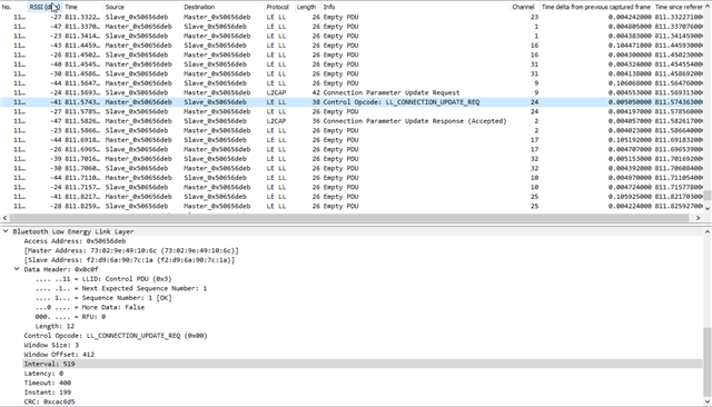
Phone – Slave connection:
Sniffer output:
Received commands:
0> <info> app: Min Interval: 6, Max Interval: 6, Con. Latency: 0, Sup. TimeOut: 2000
0> <info> app: Min Interval: 39, Max Interval: 39, Con. Latency: 0, Sup. TimeOut: 2000
0> <info> app: Min Interval: 519, Max Interval: 519, Con. Latency: 0, Sup. TimeOut: 400
Master – Slave connection:
Sniffer output:
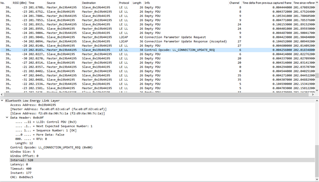
Received commands:
0> <info> app: Min Interval: 24, Max Interval: 24, Con. Latency: 0, Sup. TimeOut: 400
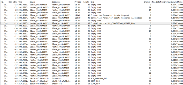
Master – Slave Connection termination (Sniffer output):
The slave requests for the connection update with suggested connection parameters as in example
#define MIN_CONN_INTERVAL MSEC_TO_UNITS(400, UNIT_1_25_MS)
#define MAX_CONN_INTERVAL MSEC_TO_UNITS(650, UNIT_1_25_MS)
#define SLAVE_LATENCY 0
#define CONN_SUP_TIMEOUT MSEC_TO_UNITS(4000, UNIT_10_MS)
And by default the master responds to the request with these parameters. To resolve the problem we tried decrease the “MAX_CONN_INTERVAL” and saw that the it has to be decreased to 250ms or even less otherwise the connection continues to fail.
For our project is important to keep the connection with MAX_CONN_INTERVAL as big as possible to save the battery life period. How is it possible to do it.
In addition we have some other questions:
- How is it possible to keep connection for a long period of time with max-connection-interval 650msecs or more?
- Why when the slave receives the connection-update-parameters, the minimum connection interval is received the same as maximum connection interval independently of sent.
- Why In registered message about connection interval can be seen only the maximum connection (called interval), latency and timeout, but not minimum connection interval?
- What is the parameter “Instant” that can be seen in the connection update message (In the sniffer wireshark)?
- According to sniffer the phone and the master respond for connection update request with two messages, but in the different order: The master previously gives “Connection Parameter Update Response (Accepted)” and then “Control Opcode: LL_CONNECTION_UPDATE_REQ” while the Phone previousely gives “Control Opcode: LL_CONNECTION_UPDATE_REQ” and then “Connection Parameter Update Response (Accepted)”. Is it possible to change the order of the commands? Can it be the source of problem too?
Thank you very much for paying attention
Best Regards
Boris Fridman

