This post is older than 2 years and might not be relevant anymore
More Info: Consider searching for newer posts

The Connection fails after some seconds with error 8 BLE_HCI_CONNECTION_TIMEOUT

Hi, everyone,

We are developing the project on nRF52832 chip that is built from master (multirole) and slaves modules.  The master program (in our case master is multirole because in some cases it must connect to telephone as a slave too) is created from “ble_app_hrs_rscs_relay” example and the slave program is created from “ble_app_hrs” example. Both projects are developed on SDK15.0.

During the work the master must establish connection for long period of time (approximately for 10 minutes).  In required time the master connects to required slave and establishes connection, but after discovering characteristics it disconnects with error 8 BLE_HCI_CONNECTION_TIMEOUT.

We tried to check the slave from telephone BLE application and saw that the slave reminds connected for a long period of time. Than we tried to check the connection establishment by the sniffer and saw that the failing happens right away after the connection update. We tried to compare the connection update parameters and saw the next difference:

Phone – Slave connection:

Sniffer output:
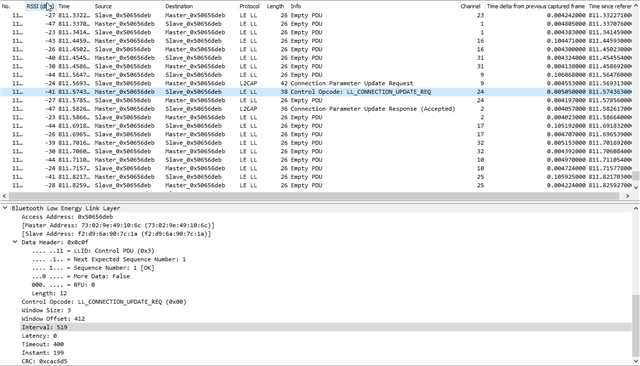
Received commands:

0> <info> app: Min Interval: 6, Max Interval: 6, Con. Latency: 0, Sup. TimeOut: 2000

 0> <info> app: Min Interval: 39, Max Interval: 39, Con. Latency: 0, Sup. TimeOut: 2000

 0> <info> app: Min Interval: 519, Max Interval: 519, Con. Latency: 0, Sup. TimeOut: 400


Master – Slave connection:

Sniffer output:
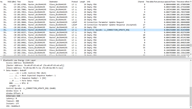
Received commands:

0> <info> app: Min Interval: 24, Max Interval: 24, Con. Latency: 0, Sup. TimeOut: 400

Master – Slave Connection termination (Sniffer output):
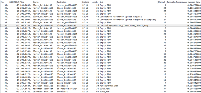
 

The slave requests for the connection update with suggested connection parameters as in example

#define MIN_CONN_INTERVAL                   MSEC_TO_UNITS(400, UNIT_1_25_MS)

 #define MAX_CONN_INTERVAL                   MSEC_TO_UNITS(650, UNIT_1_25_MS)

#define SLAVE_LATENCY                       0 

#define CONN_SUP_TIMEOUT                    MSEC_TO_UNITS(4000, UNIT_10_MS)

And by default the master responds to the request with these parameters. To resolve the problem we tried decrease the “MAX_CONN_INTERVAL” and saw that the it has to be decreased  to 250ms or  even less otherwise the connection continues to fail.

For our project is important to keep the connection with MAX_CONN_INTERVAL as big as possible to save the battery life period. How is it possible to do it.

In addition we have some other questions:

  1. How is it possible to keep connection for a long period of time with max-connection-interval 650msecs or more?
  2. Why when the slave receives the connection-update-parameters, the minimum connection interval is received the same as maximum connection interval independently of sent.
  3. Why In registered message about connection interval can be seen only the maximum connection (called interval), latency and timeout, but not minimum connection interval?
  4. What is the parameter “Instant” that can be seen in the connection update message (In the sniffer wireshark)?
  5. According to sniffer the phone and the master respond for connection update request with two messages, but in the different order: The master previously gives “Connection Parameter Update Response (Accepted)” and then “Control Opcode: LL_CONNECTION_UPDATE_REQ”       while the Phone previousely gives “Control Opcode: LL_CONNECTION_UPDATE_REQ” and then “Connection Parameter Update Response (Accepted)”. Is it possible to change the order of the commands? Can it be the source of problem too?

Thank you very much for paying attention

Best Regards

Boris Fridman

  • Hi,

    Is the BLE master a nRF52832 Development Kit, or a custom board?

    Are you seeing this issue on several BLE master devices, or only one?

    How have you configured the SoftDevice clock source and accuracy? 

    What is the value of NRF_SDH_CLOCK_LF_SRC, NRF_SDH_CLOCK_LF_RC_CTIV, NRF_SDH_CLOCK_LF_RC_TEMP_CTIV and NRF_SDH_CLOCK_LF_ACCURACY ? (You can find these values in sdk_config.h)

  • Hi, Sigurd,

    I have checked these values and they had the next values:

    NRF_SDH_CLOCK_LF_SRC                                          1 (NRF_CLOCK_LF_SRC_XTAL)

    NRF_SDH_CLOCK_LF_RC_CTIV                                  0

    NRF_SDH_CLOCK_LF_RC_TEMP_CTIV                      0

    NRF_SDH_CLOCK_LF_ACCURACY                             7  (NRF_CLOCK_LF_ACCURACY_20_PPM)


    I had solved the problem by adjusting "NRF_SDH_CLOCK_LF_ACCURACY" from "7" (20ppm) to 2 (150ppm).

    But this adjustment itself confused me: The connection stability increased with increasing permitted clock dispersion in ppm that means with decreasing the clock accuracy if I understand correctly the meaning of the value of "NRF_SDH_CLOCK_LF_ACCURACY".

    How does it happen? How decreasing the clock accuracy can increase the stability of connection? Or may it be that increasing the value of “NRF_SDH_CLOCK_LF_ACCURACY” in ppm increases the accuracy and not decreases it?

    In account of what the increasing the “NRF_SDH_CLOCK_LF_ACCURACY”’s value in ppm increases connection stability. What may be decreased or reduced in this case?

  • Higher ppm values means worse accuracy, and more clock drift over time. The SoftDevice takes this value into account in the BLE link layer timing.

    What ppm value you should use will depend on accuracy of the external LF crystal you are using. This should be listed in the datasheet of the crystal. But note that if you are using the wrong load capacitance values(C11/C12), the crystal will not have the correct oscillation frequency, and will drift more than what is stated in the datasheet. See this link.

  • Hi, Sigurd


    Thank you for your answer.

    We used the crystal from this datasheet "">www.ecsxtal.com/.../ecx-306x.pdf" with 10pF capacitors so most probably the problem was in incorrect capacitors as you "said".


    We have looked in the formula and in the Reference circuitry given by you. According to them C11=C12=2*CL-Cpin-Cpcb=12pF=2*9pF-4pF-Cpcb that means Cpcb=18pF-12pF-4pF=2pF. Is this Cpcb=2pF actual for most PCB boards where the crystal is placed as close as possible to the chip or only for PCA10040 where crystal X2 is connected to processor via SB1 and SB2 by the tracks that goes from chip to SB1&SB2 bridges and only then return back to the crystal?


    Which Cpcb should we take in account in our case if it is not equal to 2pF as in PCA10040?

  • Hi,

    Cpcb is usually lower than 1 pF. In the reference design the crystal CL is 8 pF, so we are using C11 = C12 = 2*CL - 4 pF. I.e. using that C_pcb + C_pin is approximately 4 pF. That gives C11=C12= 12pF.

    The formula is good starting point, but Cpcb could also be measured as described in this answer.


Related