This post is older than 2 years and might not be relevant anymore
More Info: Consider searching for newer posts

SAADC example unexpected results

I'm trying to use the SDK 15.0 saadc example with a potentiometer on AIN0, and I'm getting weird values.  Left pot pin connected to VDD, right pot pin to GND, center pin to P0.03(A0).  The output is reading anywhere from 42-45 if I don't touch the potentiometer - regardless of it's rotation.  If I turn it toward ground and leave it there, I'll see the values momentarily dip to into the 30s then return to the 42-45 range.  If I turn it toward VDD and leave it there, they jump up into the 50s, then return to 42-45.  Similarly, if I connect AIN0 directly to VDD or GND, I get a single reading in the 30s or 50s, then it returns to the 42-45 range.  I've tried setting up the board in the arduino IDE and the analog examples work fine there.  They'll read full range to reflect the potentiometer.  Am I misunderstanding what this example does?  I saw another question describing something similar, but it is unanswered.

Parents Reply Children
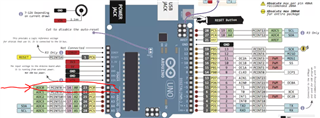
  • It is sort of documented here. I agree with you though, and I have already discussed it with the kit designers once before, but their reasoning is that A0 refers to the pinout of the standard Arduino form factor:

  • That documents what the arduino-compatible pinouts are, but doesn't disambiguate how they are labelled in your APIs.  I would argue that the printed board is in the developer's hands and in front of their eyes, so like myself, that appears to be the truth.  I had to search for quite a while to see what's really happening.  It's not explained in the example code where I looked first being new to the platform.  The example documentation mentions GPIO pin 2, which I was unsure about because it doesn't match the p0.02 notation used everywhere else.  Thanks for looking into it!

Related