This post is older than 2 years and might not be relevant anymore
More Info: Consider searching for newer posts

How to use PWM Waveform mode? Having issue with last sequence completing.

Despite all the questions on this forum for how to change PWM frequency on the fly, I found no mention of anyone using "WaveForm" mode. Perhaps it's new? There are also no examples available so I'm trying to figure it out myself.

https://infocenter.nordicsemi.com/topic/com.nordic.infocenter.nrf52832.ps.v1.1/pwm.html?cp=2_1_0_46#concept_pzc_1pw_nr

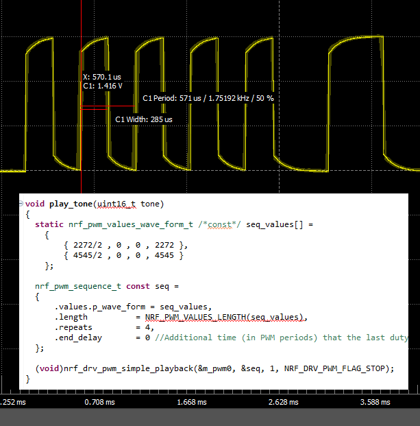
The code below works, but for some reason, the last duty-cycle and top_value will only play one cycle even though I have 'repeat' to more than zero. If I put {0,0,0,0} in addition to the sequence, the waveform will complete, but cause some unwanted behavior on my output.

TODO: Add oscilloscope screenshot.

I'm an amateur programmer, so is there an example on how to use WaveForm Mode? I plan to have multiple sequences, so an example on how to update the sequence after the initial seq_values array would be nice

The code below is heavily stripped down so it may not actually compile.

SDK Version: v15.0.0

Thanks!

#include <stdint.h>
#include <string.h>
#include "nordic_common.h"
#include "nrf.h"
#include "app_error.h"
#include "boards.h"
#include "app_timer.h"
#include "nrf_pwr_mgmt.h"
#include "nrf_delay.h"
#include "nrf_drv_pwm.h"

#include "pcb_config.h"
#include "music_tones.h"

#include "nrf_log.h"
#include "nrf_log_ctrl.h"
#include "nrf_log_default_backends.h"


static nrf_drv_pwm_t m_pwm0 = NRF_DRV_PWM_INSTANCE(0);

void play_tone(uint16_t tone);


void pwm_init()
{

  nrf_drv_pwm_config_t const config0 =
    {
        .output_pins =
        {
            SPEAKER_OUT | NRF_DRV_PWM_PIN_INVERTED, // channel 0
            NRF_DRV_PWM_PIN_NOT_USED,             // channel 1
            NRF_DRV_PWM_PIN_NOT_USED,             // channel 2
            NRF_DRV_PWM_PIN_NOT_USED,             // channel 3
        },
        .irq_priority = APP_IRQ_PRIORITY_LOWEST,
        .base_clock   = NRF_PWM_CLK_4MHz, // =250ns clock
        .count_mode   = NRF_PWM_MODE_UP,
        // "top_value" is essentially the frequency of the PWM output
        .top_value    = 1000,
        .load_mode    = NRF_PWM_LOAD_WAVE_FORM,
        .step_mode    = NRF_PWM_STEP_AUTO
    };
    APP_ERROR_CHECK(nrf_drv_pwm_init(&m_pwm0, &config0, pwm_handler));

}

void play_tone(uint16_t tone)
{

  uint16_t sequence_step_repeats = 200; // 200x250nsx2= 25ms

  static nrf_pwm_values_wave_form_t const seq_values[] =
	{
		{ NOTE_A7/2 , 0 , 0 , NOTE_A7 },
		{ NOTE_A7/2 , 0 , 0 , NOTE_A7 },
		{ NOTE_A7/2 , 0 , 0 , NOTE_A7 },
		{ NOTE_A7/2 , 0 , 0 , NOTE_A7 },
		{ NOTE_A5/2 , 0 , 0 , NOTE_A5 },
		{ NOTE_A5/2 , 0 , 0 , NOTE_A5 },
		{ 0 , 0 , 0 , 0 }
	};
  nrf_pwm_sequence_t const seq =
  {
      .values.p_wave_form = seq_values,
      .length          = NRF_PWM_VALUES_LENGTH(seq_values),
      .repeats         = sequence_step_repeats,
      .end_delay       = 0 //Additional time (in PWM periods) that the last duty cycle is to be kept after the sequence is played.
  };

  (void)nrf_drv_pwm_simple_playback(&m_pwm0, &seq, 1, NRF_DRV_PWM_FLAG_STOP);
}

int main(void)
{
  // Initialize generic
  log_init();
  timers_init();
  pwm_init();
  power_management_init();

  // Enter main loop.
  for (;;)
  {
  
    play_tone(1);
    nrf_delay_ms(1000);
    while(!nrf_drv_pwm_is_stopped(&m_pwm0)){};

  }
}

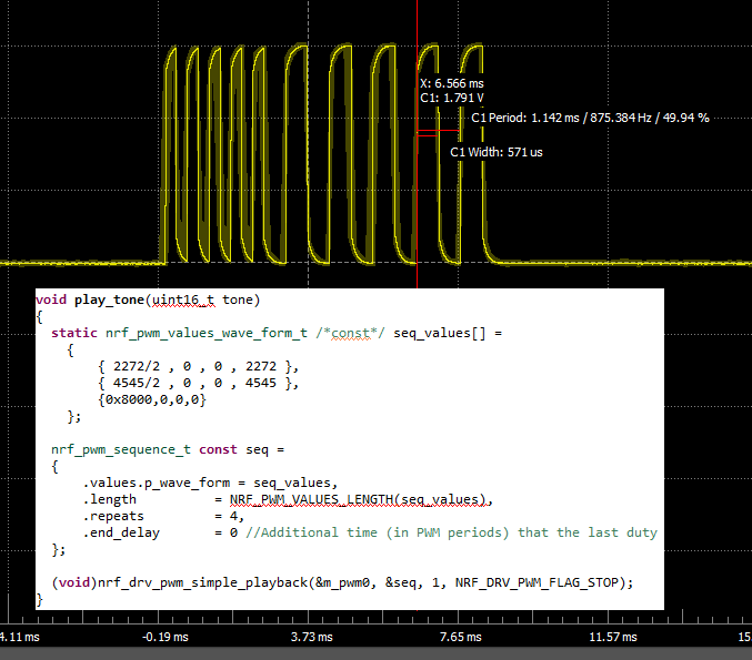
  • Here are scope captures of what I'm seeing. I actually was able to mitigate the "odd" behavior (prolonged high level) of having to add the {0,0,0,0} by simply inverting the polarity with the 15th bit by using {0x8000,0,0,0}.

    This may be a bug, though it has an easy work-around.

    waveform_missing_end_sequence

    waveform_with_complete_end_sequence

  • Hello,

    I am not sure whether I fully understand your question.

    Do you want the sequence to repeat forever, and not stop? 

    When you have a sequence defined like this:

    static nrf_pwm_values_wave_form_t /*const*/ seq_values[] =
    {
        {2272/2, 0, 0, 2272 },
        {4545/2, 0, 0, 4545 },
        {0x8000,0,0,0}
    };
    
    nrf_pwm_sequence_t const seq = 
    {
        .values.p_wave_form = seq_values,
        .length             = NRF_PWM_VALUES_LENGTH(seq_values),
        .repeats            = 4,
        .end_delay          = 0
    }
    
    (void)nrf_drv_pwm_simple_playback(&m_pwm0, &seq, 1, NRF_DRV_PWM_FLAG_STOP);

    Then the signal (since you only use one channel), will use the first column of seq_values, 2272/2, 4545/2, 0x8000

    The number of repeats of each value is seq.repeats times (4 in your case), and the output will go to HIGH when it is finished, if you have SPEAKER_OUT |NRF_DRV_PWM_PIN_INVERTED in config0, and you use the flag NRF_DRV_PWM_FLAG_STOP.

    This means that when the sequence is done, the PWM peripheral will release the GPIO, and it will get the value NRF_DRV_PWM_PIN_INVERTED.

    Note that this is the only place that NRF_DRV_PWM_PIN_INVERTED is used, when the pin is not controlled by the PWM peripheral. The polarity of the pin while the pin is used by the PWM peripheral is dependent on the msb of seq_values[], which is the bit that decides whether the pin goes from high to low or low to high when the counter hits the value of the bits 0-15 in seq[].

    If you want the signal to continue forever, you can use the flag NRFX_PWM_FLAG_LOOP instead of NRF_DRV_PWM_FLAG_STOP.

    Best regards,

    Edvin

  • Hi Edvin,

    Thanks for your response. The explanation about the inverted pin is helpful. Here are my two questions/points.

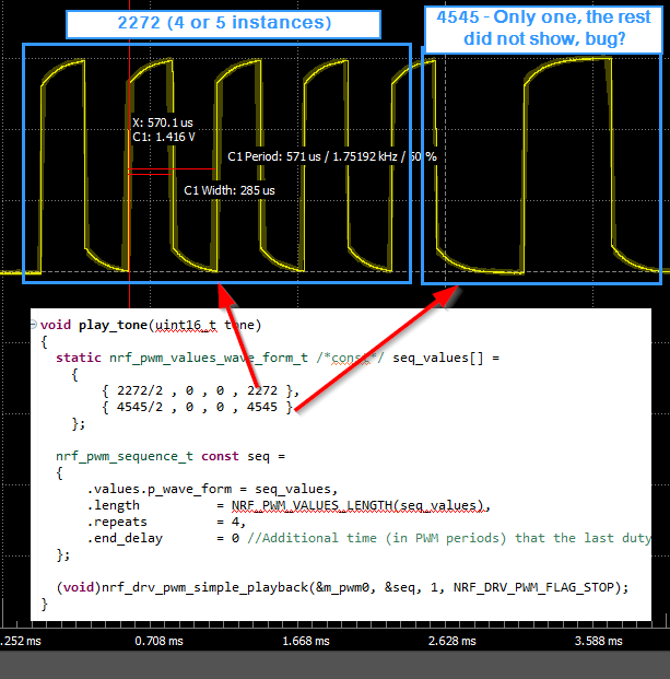
    1) I think there is a bug in the waveform driver. I've annotated my screenshot to show that I expect four sequences of 4545 frequency value, but only get one pulse. The "fix" to mitigate this behavior is adding the third sequence of 0x8000.

    waveform_missing_end_sequence annotated

    2) If there is a complete example program of PWM WaveForm mode available from Nordic? I would like one.

    Thanks.

  • Not an answer to your question, but a simple tip for more accurate 'scope waveform display in case you are not familiar with the probe adjustment; look for the small screw adjustment on the probe (either at the probe end or at the connector end) and adjust with a plastic screwdriver to square up the 'scope display by matching the probe impedance to the 'scope.

  • Hello,

    I see now. I tried your snippet, and I see that the last sequence only has one pulse. I thought it had more, but that it was cropped away from the screenshot.

    I don't know why it does that. Let me ask someone who has worked on the PWM drivers. I will get back to you.

    Best regards,

    Edvin

Related