Hi
I'm studying at university and working on my thesis. What I'm doing with a remote control and I want to measure the impedance of the antenna, because I want to be documented. I have an idea I saw on the internet as well as similar solutions. So it would be on the top side of the PCB with a 0 ohm resistance, which is the standard used at the PCB antenna base thereof is connected to the measurement and jumpered U.FL (IPX / AMC) type connector, but it is on the lower side. The question would be, how it works this way?
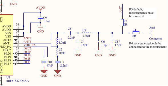
Schemtic
##
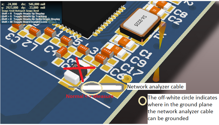
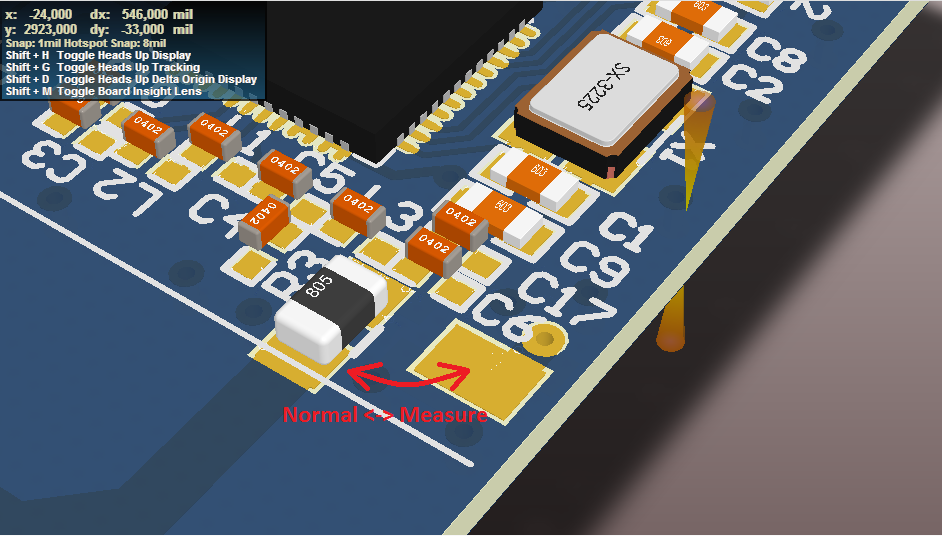
Top layer
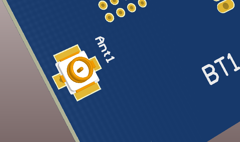
Bottom layer