This post is older than 2 years and might not be relevant anymore
More Info: Consider searching for newer posts

GPIOTE Interrupt

I'm learning about GPIOTE and PPI and looking at an example I come to the following code but now it act incorrectly. So as you can see I'm enabling the interrupt for GPIOTE channel 0:

NRF_GPIOTE->INTENSET = GPIOTE_INTENSET_IN0_Msk;

But when the IRQHandler is called this is what I get: image description

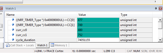
I expected CC[1] to be 0 but instead it is the value when the signal go HITOLOW!

Here is the signal I'm capturing: image description

CC[0] is cursor #3 (LOWTOHIGH) and CC[1] is cursor #4 (HIGHTOLOW). Timer starts to count at #2!

void GPIOTE_IRQHandler(void)
{
    
		curr_cc1 = NRF_TIMER1->CC[1];	
		curr_cc0 = NRF_TIMER1->CC[0];  

    // Clear the event causing the interrupt.
    NRF_GPIOTE->EVENTS_IN[0] = 0;  
		NRF_GPIOTE->EVENTS_IN[1] = 0;
	
		NRF_TIMER1->TASKS_STOP = 1;
}

/** @brief Function for initializing the GPIO Tasks/Events peripheral.
*/
static void gpiote_init(void)
{
    NVIC_EnableIRQ(GPIOTE_IRQn);

    nrf_gpio_cfg_sense_input(ECHO, NRF_GPIO_PIN_NOPULL, NRF_GPIO_PIN_SENSE_LOW);

    // Enable interrupt on input 1 event.
    NRF_GPIOTE->INTENSET = GPIOTE_INTENSET_IN0_Msk;

    // Configure GPIOTE channel 0 to generate event on input pin low-to-high transition.
    nrf_gpiote_event_config(0, ECHO, NRF_GPIOTE_POLARITY_LOTOHI);
	
		// Configure GPIOTE channel 1 to generate event on input pin high-to-low transition.
    // Note that we can connect multiple GPIOTE events to a single input pin.
    nrf_gpiote_event_config(1, ECHO, NRF_GPIOTE_POLARITY_HITOLO);
	
}

/** @brief Function for initializing the PPI peripheral.
*/
static void ppi_init(void)
{
    // Configure PPI channel 0 to capture Timer 1 value into  the CC[0] register.
    // This is achieved when GPIOTE detects Low-to-High transition on pin INPUT_PIN_NUMBER.
    NRF_PPI->CH[0].EEP = (uint32_t)&NRF_GPIOTE->EVENTS_IN[0];
    NRF_PPI->CH[0].TEP = (uint32_t)&NRF_TIMER1->TASKS_CAPTURE[0];

    // Configure PPI channel 1 to capture Timer 1 value into CC[1] register.
    // This is achieved when GPIOTE detects High-to-Low transition on pin INPUT_PIN_NUMBER.
    NRF_PPI->CH[1].EEP = (uint32_t)&NRF_GPIOTE->EVENTS_IN[1];
    NRF_PPI->CH[1].TEP = (uint32_t)&NRF_TIMER1->TASKS_CAPTURE[1];

    // Enable only PPI channels 0 and 1.
    NRF_PPI->CHEN = (PPI_CHEN_CH0_Enabled << PPI_CHEN_CH0_Pos)
                  | (PPI_CHEN_CH1_Enabled << PPI_CHEN_CH1_Pos);
}
  • Hi

    I suspect that you are trying to build upon the gpiote_example in the nRF51 SDK. For setup of interrupts and interrupt handler, you might also benefit of looking at e.g. the rtc_example in the SDK.

    I am also pretty unsure of what you are trying to achieve, so please clarify your problem.

    You have not shown in your code your Timer configuration. TIMER1->CC[0] and TIMER1->CC[1] values should be the same as you set them when you initialize the timer. How it works is that you set a CC[X] compare register and then you start the TIMER. When the TIMER value is equal to the CC[X] value, a timer event is generated. Perhaps these simple timer examples will help you if you have doubts about how the TIMER actually works. Timer information is also available in the nRF51 Series Reference Manual.

  • I'm trying to capture the signal that you see in channel 2 of logic analyser screenshot. So I set up a gpiote task to lowtohigh event the save the timer1 count on cc[0] and another gpiote task to hightolow event that save the value on cc[1].

    On the gpiote init I enable an interrupt for the lowtohigh event and debugging the code with a breakpoint on the gpioteirqhandler I would expect to got 0 on the cc[1] instead of the hightolow value.

  • It looks like the values are being read after the GPIOTE task 1 has completed. Make sure you don't put any breakpoints in the GPIOTE_IRQHandler before reading the values of CC[0] / CC[1]. Check below for breakpoint positioning.

    From the documentation of GPIOTE abstraction:

    The GPIOTE users are responsible for configuring all their corresponding pins, except the SENSE field, which should be initialized to GPIO_PIN_CNF_SENSE_Disabled.

    Although you are not using the abstraction, it might have to do something with Sense Low. I don't configure the sense field in my project, so I am not sure about this.

    Try changing:

    nrf_gpio_cfg_sense_input(ECHO, NRF_GPIO_PIN_NOPULL, NRF_GPIO_PIN_SENSE_LOW);
    

    To:

    nrf_gpio_cfg_input(ECHO, NRF_GPIO_PIN_NOPULL);
    

    Enable Interrupts on GPIOTE after you have cleared the pending flags like this:

    NVIC_DisableIRQ(GPIOTE_IRQn);
    NVIC_ClearPendingIRQ(GPIOTE_IRQn);
    
    NRF_GPIOTE->INTENSET = 0x00000001;// enable interrupts for config[n] pins, n = 0 in this case so bitmask is 0x01
    
    NVIC_SetPriority(GPIOTE_IRQn, 3); //optional: set priority of interrupt
    NVIC_EnableIRQ(GPIOTE_IRQn);
    

    Try to separate GPIOTE events in GPIOTE_IRQHandler and put breakpoints after reading CC values:

    if(NRF_GPIOTE->EVENTS_IN[0] == 1)
    {
    	curr_cc0 = NRF_TIMER1->CC[0];
    	curr_cc1 = NRF_TIMER1->CC[1]; //keep this if you need it
    	NRF_GPIOTE->EVENTS_IN[0] = 0;  //this is where you should set breakpoint to make sure CC[0] and cc[1] don't change while you are in breakpoint
    }
    
    if(NRF_GPIOTE->EVENTS_IN[1] == 1) //will run only if you intenset event 1
    {
    	curr_cc0 = NRF_TIMER1->CC[0]; //keep this if you need it
    	curr_cc1 = NRF_TIMER1->CC[1];
    	NRF_GPIOTE->EVENTS_IN[1] = 0;  //this is where you should set breakpoint to make sure CC[0] and cc[1] don't change while you are in breakpoint
    }
    
Related