This post is older than 2 years and might not be relevant anymore
More Info: Consider searching for newer posts

Design Review of NRF51822-QFAA board

Hello,

Greetings from India!

I would like to have my design review by your engineers or any concerned person in the related field. The design is not yet complete but the reference layout is taken from here.
I am using inverted F antenna with default passive pi-network as given in the reference layout.

I have attached the gerbers below at your perusal for review.

Please provide me with the detailed analysis as I am a beginner in the RF world. Also I do not have any spectrum analyzer to carry out any necessary testing. If possible please provide me with a correct design(preferred in EagleCAD) .

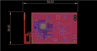
Below is the snapshot of the board designed in Eagle.

Hoping to hear from you soon.

Tracker.zip

  • As mentioned earlier do not use 0603 for matching components.  At 2.4GHz, it's about 10 degrees just going from one side of the device to the other.  Matching is a pain.  Use 0402 or preferably 0201.

    You failed to stitch the interior of the board.  The whole things needs to be stitched.  

    You should use the Johanson matched balun for it.  Likely it will work without a lot of post matching.  Also, you get a harmonic filter in the same package and a smaller footprint than all those discretes.

    You should model the antenna.  Use the free version of Sonnet.  It will easily model that antenna and the learning curve is easy. This way you can get the antenna close to 50ohm in the model and the board will come out close.

  •  Thanks for your review!

    You failed to stitch the interior of the board.  The whole things needs to be stitched.

    By stitching you mean to connect the 2 layers with via, right? Both the planes are GND.
    I will do it eventually as I go through the design process.

    You should use the Johanson matched balun for it.

    Ok. I am getting these parts from Mouser, please verify the following:
    1. 2450BM14E0003T
    2. Chip Antenna
    This is the antenna I prefer to use along with the balun. Please verify, if I need any additional filter/matching network along with the balun.
    Actually I do not prefer to use the discrete matching network. They are pain in the a*s!

    You should model the antenna.  Use the free version of Sonnet.  It will easily model that antenna and the learning curve is easy. This way you can get the antenna close to 50ohm in the model and the board will come out close.

    Is this step necessary if I use the chip antenna?

    Waiting for your reply.

    Also, you get a harmonic filter in the same package and a smaller footprint than all those discretes.

    I did not understand by what you meant by harmonic filter. Please elaborate as I am a noob in RF designing.

  • 1. Yes I meant vias on the interior.  Just because they are both ground doesn't mean they are at the same potential all the time.

    2. I'm sorry I simply don't have the time right now to review individual parts.  Printed antennae like your F antenna have much better efficiency than chip antennae therefore greater range.  Chip antennae are easier to get to 50 ohm by rigidly following the design guidelines.  Take your pick.

    3. If you use a chip and rigidly follow the design specs yes you will probably get something that works well without a lot of effort.

    4. Just google harmonic filter.

  • I am just worried about the inverted F antenna tuning. So can I avoid the discrete matching network and use this 2450BM14E0003T balun instead?

Related