This post is older than 2 years and might not be relevant anymore
More Info: Consider searching for newer posts

Copied PCB design & Assembled SparkFun nRF52832 Breakout Board. But it is not programmable!

Hello, 

I purchased a nRF52 DK  board and sparkfun nrf52832 breakout board, and was successful with blinking the LED on the breakout board. 

In order to test if I would manipulate the PCB, I needed to see if I could successfully assemble the PCB. Thus, I  copied the PCB design of Sparkfun nRF52832 Breakout Board from the open source, sent them to manufacturer, and assembled them. All the component values are correct, because I copied them exactly from the Sparkfun Opern source.    

However, after I assembled the board and tried to program it with nRFgo Studio, there is a error saying "No Device connected, or readback protection may be set". In order to make sure it is not a soldering problem, I assembled multiple boards, but they all ran into the same error. It looks like nRFgo Studio cannot recognize the board. 

All the components are exactly the same. Copied the schematic, BOM, and made sure they are properly soldered. The only difference is that on the MCU it says," N52832 QFAAE1" while on the breakout board it says "QFAAB0" but I don't think this makes a difference. 

Do I have to boot the mcu with something? or is there a step I need to take before programming the chip? How can I make nRFgo studio recognize this "custom" board? (well, "copied" to be exact". 

It would be a huge help if this problem can be solved..... Thank you!

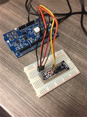
included a picture just for a reference. 

Parents
  • All the component values are correct

    Having the values correct is necessary - but not sufficient:

    www.dailymail.co.uk/.../Playing-wrong-notes-iconic-Morecambe-Wise-sketch.html

    Are you sure that you have placed them all in the correct places?

    And that they are all correctly oriented?

    And that you haven't damaged any?

    In order to make sure it is not a soldering problem, I assembled multiple boards, but they all ran into the same error.

    Maybe you made the same mistake multiple times?

    Maybe you made different mistakes on each board?

    These are very fine components, so even tiny mistakes can be significant. It is very easy to make mistakes!

    is there a step I need to take before programming the chip?

    Before assembling any components, did you examine and test the bare boards?

    After assembling the boards, have you tested that you're getting correct voltages at key points?

    Have you used an oscilloscope to check key things like oscillators running, SWD lines working, etc?

    It seems far from certain that your hardware is working - certainly too early to be wondering about software tools ...

Reply
  • All the component values are correct

    Having the values correct is necessary - but not sufficient:

    www.dailymail.co.uk/.../Playing-wrong-notes-iconic-Morecambe-Wise-sketch.html

    Are you sure that you have placed them all in the correct places?

    And that they are all correctly oriented?

    And that you haven't damaged any?

    In order to make sure it is not a soldering problem, I assembled multiple boards, but they all ran into the same error.

    Maybe you made the same mistake multiple times?

    Maybe you made different mistakes on each board?

    These are very fine components, so even tiny mistakes can be significant. It is very easy to make mistakes!

    is there a step I need to take before programming the chip?

    Before assembling any components, did you examine and test the bare boards?

    After assembling the boards, have you tested that you're getting correct voltages at key points?

    Have you used an oscilloscope to check key things like oscillators running, SWD lines working, etc?

    It seems far from certain that your hardware is working - certainly too early to be wondering about software tools ...

Children
No Data
Related