Hi,
I am trying to configure the nRF52810 clock setup to accept the LF CLK source from a pin on stm32l4xx on a custom board without much luck. My setup works correctly if I use RC as the source for the LF CLK, but I would much rather use the clock output from the stm.
Chips: STM32L451, nRF52810
nRF SDK: 15.2
IDE: SEGGER Embedded Studio
The code on the nRF is based off the "ble_app_template_pca10040e_s112" example.
The hardware setup is as follows:
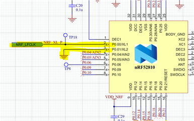
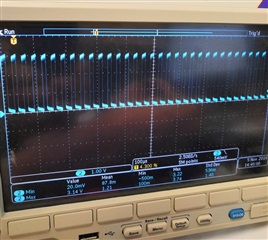
nRF XL2 is connected to GND and nRF XL1 is connected to the 32.768KHz clock signal from the STM. This clock signal is being output by the STM on pin PA2 (the LSCO pin) which is configured to output LSE. LSE is driven by an external crystal and we cannot have an additional crystal for the nRF due to layout reasons. I have confirmed that the STM is correctly generating the 32.768KHz CLK separately.
In terms of software:
I am initialising the registers manually before enabling the SoftDevice as per the advice in a recent DevZone post (devzone.nordicsemi.com/.../121423. Code can be seen below, placed at the start of main():
NRF_CLOCK->LFCLKSRC = (CLOCK_LFCLKSRC_SRC_Xtal << CLOCK_LFCLKSRC_SRC_Pos);
NRF_CLOCK->LFCLKSRC |= (CLOCK_LFCLKSRC_BYPASS_Enabled << CLOCK_LFCLKSRC_BYPASS_Pos);
NRF_CLOCK->LFCLKSRC |= (CLOCK_LFCLKSRC_EXTERNAL_Enabled << CLOCK_LFCLKSRC_EXTERNAL_Pos);
NRF_CLOCK->EVENTS_LFCLKSTARTED = 0;
NRF_CLOCK->TASKS_LFCLKSTART = 1;
while (NRF_CLOCK->EVENTS_LFCLKSTARTED == 0)
{
}
NRF_CLOCK->EVENTS_LFCLKSTARTED = 0;
This code sits in the while loop forever. And I have even tried triggering TASKS_LFCLKSTART manually through the registers in SEGGER. Is it still the case that the SoftDevice API does not support an external LFCLK? Is setting the clock up manually before enabling the SD still the recommended workaround for this?
The relevant parts in sdk_config.h for my clock setup are as follows:
// </h>
//==========================================================

// <h> Clock - SoftDevice clock configuration

//==========================================================
// <o> NRF_SDH_CLOCK_LF_SRC  - SoftDevice clock source.

// <0=> NRF_CLOCK_LF_SRC_RC
// <1=> NRF_CLOCK_LF_SRC_XTAL
// <2=> NRF_CLOCK_LF_SRC_SYNTH

#ifndef NRF_SDH_CLOCK_LF_SRC
#define NRF_SDH_CLOCK_LF_SRC 1 //0 when STM32 LFCLK not working
//#define NRF_SDH_CLOCK_LF_SRC 0 //RC
#endif

// <o> NRF_SDH_CLOCK_LF_RC_CTIV - SoftDevice calibration timer interval.
#ifndef NRF_SDH_CLOCK_LF_RC_CTIV
#define NRF_SDH_CLOCK_LF_RC_CTIV 0 //16 when STM32 LFCLK not working
//#define NRF_SDH_CLOCK_LF_RC_CTIV 16 //RC
#endif

// <o> NRF_SDH_CLOCK_LF_RC_TEMP_CTIV - SoftDevice calibration timer interval under constant temperature.
// <i> How often (in number of calibration intervals) the RC oscillator shall be calibrated
// <i>  if the temperature has not changed.

#ifndef NRF_SDH_CLOCK_LF_RC_TEMP_CTIV
#define NRF_SDH_CLOCK_LF_RC_TEMP_CTIV 0 //2 when STM32 LFCLK not working
//#define NRF_SDH_CLOCK_LF_RC_TEMP_CTIV 2 //RC
#endif

// <o> NRF_SDH_CLOCK_LF_ACCURACY  - External clock accuracy used in the LL to compute timing.

// <0=> NRF_CLOCK_LF_ACCURACY_250_PPM
// <1=> NRF_CLOCK_LF_ACCURACY_500_PPM
// <2=> NRF_CLOCK_LF_ACCURACY_150_PPM
// <3=> NRF_CLOCK_LF_ACCURACY_100_PPM
// <4=> NRF_CLOCK_LF_ACCURACY_75_PPM
// <5=> NRF_CLOCK_LF_ACCURACY_50_PPM
// <6=> NRF_CLOCK_LF_ACCURACY_30_PPM
// <7=> NRF_CLOCK_LF_ACCURACY_20_PPM
// <8=> NRF_CLOCK_LF_ACCURACY_10_PPM
// <9=> NRF_CLOCK_LF_ACCURACY_5_PPM
// <10=> NRF_CLOCK_LF_ACCURACY_2_PPM
// <11=> NRF_CLOCK_LF_ACCURACY_1_PPM

#ifndef NRF_SDH_CLOCK_LF_ACCURACY
#define NRF_SDH_CLOCK_LF_ACCURACY 7 //1 when STM32 LFCLK not working
//#define NRF_SDH_CLOCK_LF_ACCURACY 1 //RC
#endif

// </h>
// </e>

// <e> NRFX_CLOCK_ENABLED - nrfx_clock - CLOCK peripheral driver
//==========================================================
#ifndef NRFX_CLOCK_ENABLED
#define NRFX_CLOCK_ENABLED 1
#endif
// <o> NRFX_CLOCK_CONFIG_LF_SRC  - LF Clock Source

// <0=> RC
// <1=> XTAL
// <2=> Synth
// <131073=> External Low Swing
// <196609=> External Full Swing

#ifndef NRFX_CLOCK_CONFIG_LF_SRC
#define NRFX_CLOCK_CONFIG_LF_SRC 1
//#define NRFX_CLOCK_CONFIG_LF_SRC 0 // Internal RC
#endif

// <e> NRF_CLOCK_ENABLED - nrf_drv_clock - CLOCK peripheral driver - legacy layer
//==========================================================
#ifndef NRF_CLOCK_ENABLED
#define NRF_CLOCK_ENABLED 1
#endif
// <o> CLOCK_CONFIG_LF_SRC  - LF Clock Source

// <0=> RC
// <1=> XTAL
// <2=> Synth
// <131073=> External Low Swing
// <196609=> External Full Swing

#ifndef CLOCK_CONFIG_LF_SRC
#define CLOCK_CONFIG_LF_SRC 1
//#define CLOCK_CONFIG_LF_SRC 0
#endif
I have left in the configuration I use for the RC oscillator (commented out in the snippet above) to demonstrate the setup I use which works (albeit using the RC osc). I am unsure what else I can try to get this working as using the RC osc as the LF CLK source is not ideal.
The previous post I linked above talks about grounding XL2 being an issue and I have also found a post here (devzone.nordicsemi.com/.../118947 which talks about leaving XL2 floating or connecting XL1 and XL2 to the CLK simultaneously. Could this be a potential solution?
Thanks for reading and apologies if I have missed out any key information.
Kind regards,
Andy