This post is older than 2 years and might not be relevant anymore
More Info: Consider searching for newer posts

RF impedance of Nordic on dev kit

Hi,

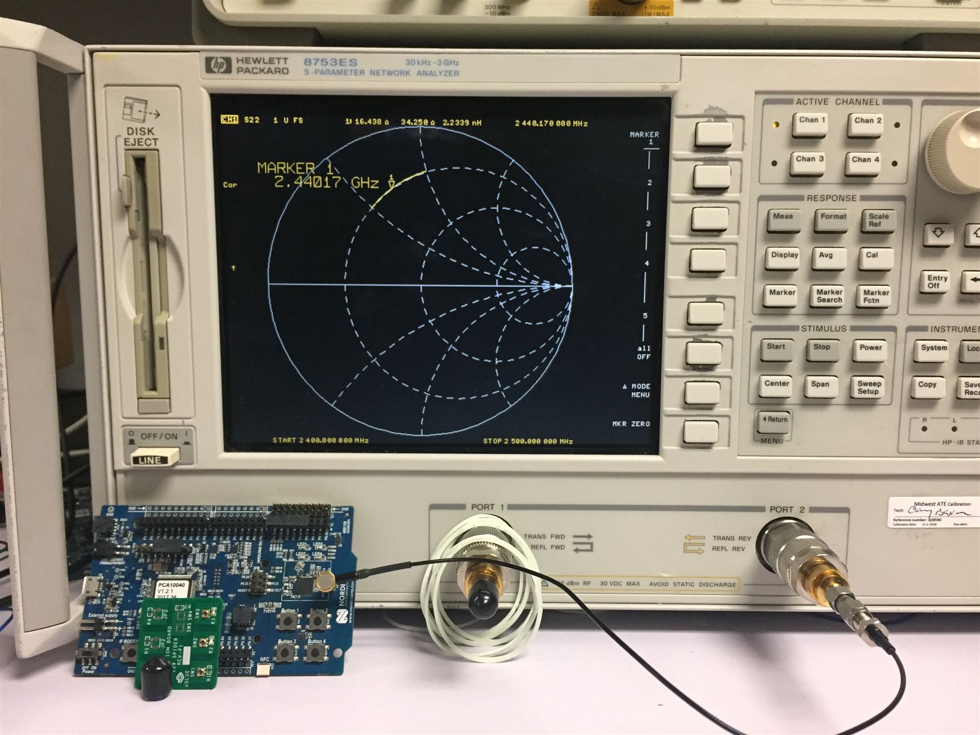
NRF52 DK has an RF switch which can be used for looking into the Nordic and observe the impedance using a VNA. I observed the same impedance in RX, TX and power off so I used power off for these experiments.

Using my VNA it looks like the impedance is 10 + 8j. Which is very similar to a 50ohm source impedance followed by 1pF shunt C and 4nH series L... Is the impedance looking in to Nordic supposed to be 50ohms or 10+8j?

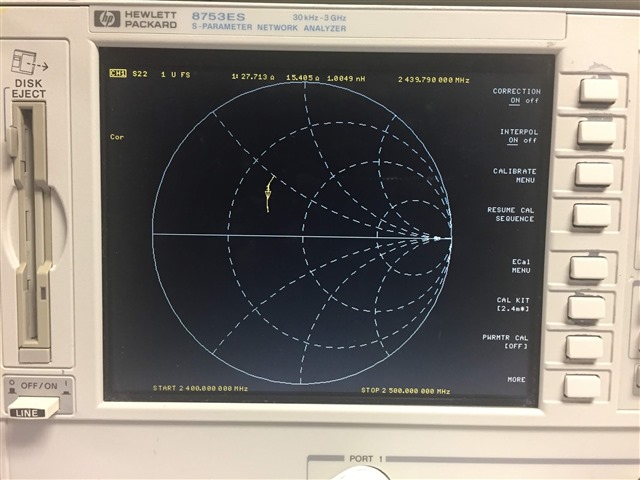
Maybe I have a calibration issue with my VNA. I have to calibrate-out the VNA-to-switch cable and the RF switch, both Murata (MM8130-2600RA2 and MXHS83QE3000) so we built a custom calibration board (open/short/50ohm). But now there is a real issue setting up this "custom calibration kit" on my VNA, I don't know what parameters to plug in for offset delay and offset loss. I tried setting them to negligable values but Nordic still doesn't look like 50ohms.

Can you recommend a calibration flow? What is the Nordic impedance? Do calibration kits exist for these Murata switches?

Thanks so much!

Parents
  • Hi,


    Something is not right here, this should be much closer to 50 ohm. Not perfect, but close.


    I have no idea if there exist any cal kits for this connector, but I doubt it. What you could do is calibrate using a coax cal kit which you probably have, and adjust the offset by looking at the impedance, increase it until the impedance is 'open'.

    What are you trying to do? I might be able to suggest a better way forward if I knew.


    Best regards,

    Andreas

Reply
  • Hi,


    Something is not right here, this should be much closer to 50 ohm. Not perfect, but close.


    I have no idea if there exist any cal kits for this connector, but I doubt it. What you could do is calibrate using a coax cal kit which you probably have, and adjust the offset by looking at the impedance, increase it until the impedance is 'open'.

    What are you trying to do? I might be able to suggest a better way forward if I knew.


    Best regards,

    Andreas

Children
  • Hi Andreas,

    Thanks for your response. I attach an image with my set-up.

    You can see that after my calibration the Nordic impedance is not 50ohms. In the screen shot is our custom calibration board which I'm using, but it's likely my calkit settings are not correct (c0,c1,c2,c3,offset delay, offset loss, offset impedance). I've played with those settings a lot but still post calibration, open has a large imaginary component...

    If we were to use the coax calibration kit, would that require acquiring a Murata RF switch to coax converter?

    What we are actually doing is making a System-in-package SiP. The matching network sits outside the SiP meaning between the Nordic and the matching network there is a bond wire and several mm of trace. Therefore we want to customize the matching network.

    Based on this information, can you suggest a better way forward?

  • I found a blog which better explained how to fix my calibration issues. It now looks like my probe is calibrated, my open short and load impedances appear in the correct place. However, the Nordic dev kit in RX test mode has input impedance looking like this. Is this expected? Or do you think I still have a calibration issue?

  • Hi,


    This seems fairly correct, when not powered the impedance should be further from 50 ohm as you see. I would still expect it to be in the capacitive half, but this could possibly be due to the extra length of trace between the switch and the inductor.

    Using a coax calibration kit could be done either with this Murata switch, or by soldering a coaxial cable directly to the output of the matching network. We normally do the latter.


    I would not focus too much on the impedance though, and if so you should consider the load impedance, i.e. the impedance seen by the nRF52832 both at fundamental and harmonics. Fundamental is not the issue, but the harmonic rejection will vary a lot with various matching network. You need to measure this directly to know if you will be compliant or not, and possibly tune the components after you have received your HW samples.


    Best regards,

    Andreas

Related