Hi, I'm trying to use SPI to control an RF module to send audio data from one microcontroller to another. The parts and software I'm working with are:
- NRF52 Development Kit
- SDK 14.2.0
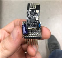
- NRF24L01+ Module
- NRF24 library for Arduino using SPI (https://github.com/martinbudden/NRF24)
I need one NRF52 to control an NRF24L01+ to act as a transmitter sending data and the other acting as a receiver; these roles will never need to change and this will be the only NRF24L01+ pair for this project. I've edited the NRF24 libraries from Github to use Nordic's functions instead of Arduino's to avoid having to include everything Arduino (changed delay(#) to nrf_delay_ms(#), using nrf SPI driver instead of Arduino's SPI, etc.). I am having problems getting the two devices to actually communicate with one another despite getting them to (seemingly) work on their own individually. The transmitter says it is transmitting, the receiver says it is waiting to receive, so I believe the initialization to be incorrect on one or both ends. For now all I care about is getting any data across and I can handle getting it up to speed and sending audio files later.
Strange things I've noticed thus far:
- SPI with the NRF24L01+ only seems to work at 1Mbps
- In order to not get garbage over SPI I needed to send a NOP first during initialization and then proceed as normal
- Datasheet mentions the contents of the STATUS register are sent out whenever SS goes from high to low, seemed to be fixed by condensing as many SPI commands into single transmissions instead of using separate enable/ disable commands for the GPIO
- Writing over the default address in either receive data pipes 0 or 1 did not seem to change their values, they output the same before and after (0xE7E7E7E7E7 for data pipe 0 and 0xC2C2C2C2C2 for data pipe 1).
Here's the print outs I'm getting from my receiver and transmitter test code so far (the data is all in hex with SPI's MOSI in the left column and MISO in the right column):
RECEIVER
Init
FF	00
Config setup
20	07
02	0E
RF setup
26	07
08	00
Set channel to #1
25	0E
01	00
Set Rx Mode
20	0E
03	00
27	0E
70	00
read address pipe line 1
0B	0E
FF	C2
FF	C2
FF	C2
FF	C2
FF	C2
	address: C2 C2 C2 C2 C2
writing address hopefully
2B	0E
41	07
6C	07
6D	07
61	07
6F	07
read address again
0B	07
41	C2
6C	C2
6D	C2
61	C2
6F	C2
	address: C2 C2 C2 C2 C2
read payload if available
17	0E
FF	11
read payload if available
17	0E
FF	11
TRANSMITTER
Init
FF	00
Config setup
20	07
02	2E
RF setup
26	07
08	00
Set channel to #1
25	2E
01	00
Flush TX
E1	2E
Write payload
A0	07
4E	2E
6F	00
72	00
64	00
69	00
63	00
00	00
Set to TX mode
20	07
02	00
27	2E
70	00
Flush TX
E1	2E
Write payload
A0	07
4E	2E
6F	00
72	00
64	00
69	00
63	00
00	00
Set to TX mode
20	07
02	00
27	2E
70	00
Flush TX
E1	2E
I'm initializing SPI with:
static const nrf_drv_spi_t spi = NRF_DRV_SPI_INSTANCE(SPI_INSTANCE);

/* ... */

void spi_init()
{
    nrf_drv_spi_config_t spi_config = NRF_DRV_SPI_DEFAULT_CONFIG;

    spi_config.ss_pin   = SPI_SS_PIN;
    spi_config.miso_pin = SPI_MISO_PIN;
    spi_config.mosi_pin = SPI_MOSI_PIN;
    spi_config.sck_pin  = SPI_SCK_PIN;
    spi_config.frequency = NRF_DRV_SPI_FREQ_1M;

    APP_ERROR_CHECK(nrf_drv_spi_init(&spi, &spi_config, spi_event_handler, NULL));
}
Are there any libraries or methods I could be using to more easily interface with the NRF24L01+'s than reusing an Arduino library? I'm going to continue experimenting with SPI commands, timings, ordering, and initialization to see if I can get it working on my own for the time being unless I can find something better.