This post is older than 2 years and might not be relevant anymore
More Info: Consider searching for newer posts

Setup for blind vias in 4 layers PCB

Hi,

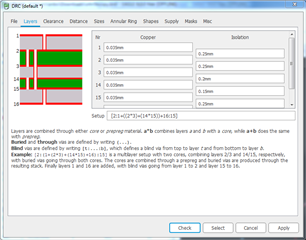
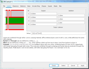
I started a 4 layers PCB design in cad-soft Eagle. In nrf52840 ref design they are using blind vias in 1 to 2 layer, so I'm guessing below DRC layer setup is correct for my requirement. 

[2:1+((2*3)+(14*15))+16:15]


Please correct me if I'm wrong also is there any recommended size blind vias?
 
Any help is appreciated.

Parents
  • Hi,


    Looking at your DRC setup:


    The reference design as you say only has blind vias between 1 and 2. Unless you need the buried and blind ones, for some other reason, you can probably remove these to save some fabrication cost.


    The reference design should have this DRC setup:


    You are of course free to expand upon this as you like, but the blind vias from top to 2, and through(or mix of blind/buried if you prefer) via from top to bottom are a minimum requirement. See this Appnote for recommendations on via dimensions.


    PS: you can find Eagle library files for nRF52840 here.


    Best regards,

    Andreas

Reply
  • Hi,


    Looking at your DRC setup:


    The reference design as you say only has blind vias between 1 and 2. Unless you need the buried and blind ones, for some other reason, you can probably remove these to save some fabrication cost.


    The reference design should have this DRC setup:


    You are of course free to expand upon this as you like, but the blind vias from top to 2, and through(or mix of blind/buried if you prefer) via from top to bottom are a minimum requirement. See this Appnote for recommendations on via dimensions.


    PS: you can find Eagle library files for nRF52840 here.


    Best regards,

    Andreas

Children
No Data
Related