This post is older than 2 years and might not be relevant anymore
More Info: Consider searching for newer posts

How to change qspi_pca10056 pin setting and command setting

Hi Guys,

I'm interested to get guideline on how could I customized the qspi example from nordic in terms of pins and command. I don't see any different between MX25R6435F vs S25FL064L chipset

I was trying to change the qspi example code and unsuccessful control the qspi using the following setting.

#define QSPI_CSN NRF_GPIO_PIN_MAP(0,19)
#define QSPI_IO0 NRF_GPIO_PIN_MAP(0,21)
#define QSPI_IO1 NRF_GPIO_PIN_MAP(0,20)
#define QSPI_IO2 NRF_GPIO_PIN_MAP(0,22)
#define QSPI_IO3 NRF_GPIO_PIN_MAP(0,24)
#define QSPI_SCK NRF_GPIO_PIN_MAP(1,0)

And the I did some change to some of the header as below

nrfx_qspi.h

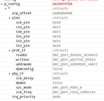
#define NRFX_QSPI_DEFAULT_CONFIG                                        \
{                                                                       \
    .xip_offset  = NRFX_QSPI_CONFIG_XIP_OFFSET,                         \
    .pins = {                                                           \
       .sck_pin     = QSPI_PIN_SCK,                                \
       .csn_pin     = QSPI_PIN_CSN,                                \
       .io0_pin     = QSPI_PIN_IO0,                                \
       .io1_pin     = QSPI_PIN_IO1,                                \
       .io2_pin     = QSPI_PIN_IO2,                                \
       .io3_pin     = QSPI_PIN_IO3,                                \
    },                                                                  \
    .irq_priority   = (uint8_t)NRFX_QSPI_CONFIG_IRQ_PRIORITY,           \
    .prot_if = {                                                        \
        .readoc     = (nrf_qspi_readoc_t)NRFX_QSPI_CONFIG_READOC,       \
        .writeoc    = (nrf_qspi_writeoc_t)NRFX_QSPI_CONFIG_WRITEOC,     \
        .addrmode   = (nrf_qspi_addrmode_t)NRFX_QSPI_CONFIG_ADDRMODE,   \
        .dpmconfig  = false,                                            \
    },                                                                  \
    .phy_if = {                                                         \
        .sck_freq   = (nrf_qspi_frequency_t)NRFX_QSPI_CONFIG_FREQUENCY, \
        .sck_delay  = (uint8_t)NRFX_QSPI_CONFIG_SCK_DELAY,              \
        .spi_mode   = (nrf_qspi_spi_mode_t)NRFX_QSPI_CONFIG_MODE,       \
        .dpmen      = false                                             \
    },                                                                  \
}

nrf_drv_qspi.h

#if QSPI_PIN_SCK == NRF_QSPI_PIN_NOT_CONNECTED
    #undef QSPI_PIN_SCK
    #define QSPI_PIN_SCK  QSPI_PIN_SCK
#endif
#if QSPI_PIN_CSN == NRF_QSPI_PIN_NOT_CONNECTED
    #undef QSPI_PIN_CSN
    #define QSPI_PIN_CSN  QSPI_PIN_CSN
#endif
#if QSPI_PIN_IO0 == NRF_QSPI_PIN_NOT_CONNECTED
    #undef QSPI_PIN_IO0
    #define QSPI_PIN_IO0  QSPI_PIN_IO0
#endif
#if QSPI_PIN_IO1 == NRF_QSPI_PIN_NOT_CONNECTED
    #undef QSPI_PIN_IO1
    #define QSPI_PIN_IO1  QSPI_PIN_IO1
#endif
#if QSPI_PIN_IO2 == NRF_QSPI_PIN_NOT_CONNECTED
    #undef QSPI_PIN_IO2
    #define QSPI_PIN_IO2  QSPI_PIN_IO2
#endif
#if QSPI_PIN_IO3 == NRF_QSPI_PIN_NOT_CONNECTED
    #undef QSPI_PIN_IO3
    #define QSPI_PIN_IO3  QSPI_PIN_IO3
#endif

Target memory chip to use.

http://www.cypress.com/file/316661/download

  • The .wren field in the nrf_qspi_cinstr_conf_t structure determines whether or not a WREN command is sent automatically before your instruction. Maybe it is worth trying to either set it to false, or not sending an explicit WREN command as you do now.

    In your last call to nrf_drv_qspi_cinstr_xfer() you only have 4 instruction bytes, so you should probably use NRF_QSPI_CINSTR_LEN_4B and not NRF_QSPI_CINSTR_LEN_5B

  • Hi

    Thanks for your input, I have follow your suggestion and have the following setting, but I still not able to get it works on the read/write. I have in contact with Cypress team, please give me some time investigate with cypress team. I will come back to update the ticket if there are improvement.

    static void configure_memory()
    {
        uint8_t temporary[2] = {0x02,0x02};
        uint32_t err_code;
        nrf_qspi_cinstr_conf_t cinstr_cfg = {
            .opcode    = QSPI_STD_CMD_RSTEN,
            .length    = NRF_QSPI_CINSTR_LEN_1B,
            .io2_level = true,
            .io3_level = true,
            .wipwait   = true,
            .wren      = false
        };
    
        // Send reset enable
        err_code = nrf_drv_qspi_cinstr_xfer(&cinstr_cfg, NULL, NULL);
        APP_ERROR_CHECK(err_code);
    
        // Send reset command
        cinstr_cfg.opcode = QSPI_STD_CMD_RST;
        err_code = nrf_drv_qspi_cinstr_xfer(&cinstr_cfg, NULL, NULL);
        APP_ERROR_CHECK(err_code);
    
        // Send WREN
        cinstr_cfg.opcode = 0x06;
        err_code = nrf_drv_qspi_cinstr_xfer(&cinstr_cfg, NULL, NULL);
        APP_ERROR_CHECK(err_code);
    
        // Switch to quad spi mode
        cinstr_cfg.opcode = QSPI_STD_CMD_WRSR;
        cinstr_cfg.length = NRF_QSPI_CINSTR_LEN_2B;
        err_code = nrf_drv_qspi_cinstr_xfer(&cinstr_cfg, &temporary, NULL);
        APP_ERROR_CHECK(err_code);
    }

  • Hi 

    I would like to learn to understand and how to configure prot_if parameters.

    readoc structure

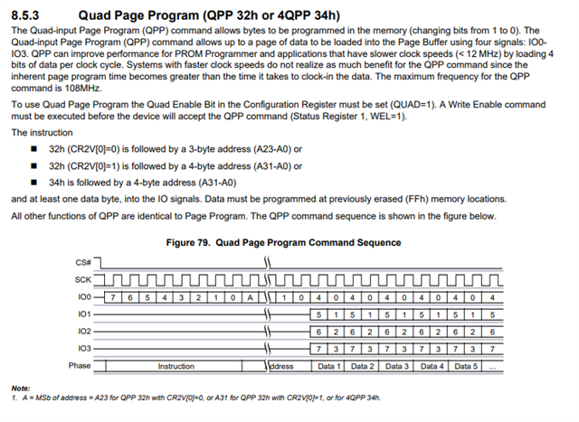
    1) NRF_QSPI_READOC_READ4IO = 0xEB which is Quad I/O Read which is same as S25F064L Quad I/O Read 0xEB?

    2)  NRF_QSPI_WRITEOC_PP4IO = 0x38 for MX25R6435F chip its 4PP? Was it the same as S25F064L 4QPP which is 0x34? 

    If I want to change those value, where can I change it? I just don't understand the code in nrf52840_bitfields.h, and how can I change if the PP4IO instruction if its different?

    /* Bits 5..3 : Configure number of data lines and opcode used for writing. */
    #define QSPI_IFCONFIG0_WRITEOC_Pos (3UL) /*!< Position of WRITEOC field. */
    #define QSPI_IFCONFIG0_WRITEOC_Msk (0x7UL << QSPI_IFCONFIG0_WRITEOC_Pos) /*!< Bit mask of WRITEOC field. */
    #define QSPI_IFCONFIG0_WRITEOC_PP (0UL) /*!< Single data line SPI. PP (opcode 0x02). */
    #define QSPI_IFCONFIG0_WRITEOC_PP2O (1UL) /*!< Dual data line SPI. PP2O (opcode 0xA2). */
    #define QSPI_IFCONFIG0_WRITEOC_PP4O (2UL) /*!< Quad data line SPI. PP4O (opcode 0x32). */
    #define QSPI_IFCONFIG0_WRITEOC_PP4IO (3UL) /*!< Quad data line SPI. PP4IO (opcode 0x38). */
    

    3) The S25F064L chip come in SPI as default setting, is the on board PCA10056 DK MX25R6435F already preconfigured with QSPI setting? If yes, How can I the command in SPI using QSPI resource?

    4) is the default QSPI sample setting same for operation below?

    http://www.cypress.com/file/316661/download

  • I need help with this topic. the topic struck for longtime, do you know any guy could help out?

    Thanks..

Related