This post is older than 2 years and might not be relevant anymore
More Info: Consider searching for newer posts

How should I use the GPIO of NRF52840 to capture a interruption of the falling edge and trigger it?

hi everyone!

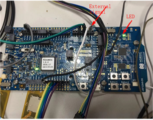
I am developing NRF52840 with the Development Kit.

I am trying to use a GPIO to o capture a external HIGH-TO-LOW signal and then trigger a LED.

I I learned the examp called pin_change_int.

But i find it's easy to capture a button signal on the board.Hard to capture the external HIGH-TO-LOW signal in my code.

Maybe u can give me some guidance.

Below is my NRF52840 Development Kit  and my code.

Thanks very much!!!

#define PIN_IN   NRF_GPIO_PIN_MAP(0,1)
#ifdef BSP_LED_1
    #define PIN_OUT BSP_LED_1
#endif
#ifndef PIN_OUT
    #error "Please indicate output pin"
#endif

void in_pin_handler(nrf_drv_gpiote_pin_t pin, nrf_gpiote_polarity_t action)
{
	UNUSED_PARAMETER(pin);
	UNUSED_PARAMETER(action);
	nrf_drv_gpiote_out_toggle(PIN_OUT);
	dataReady = 1;
}

static void gpio_init(void)
{
   ret_code_t err_code;

    err_code = nrf_drv_gpiote_init();
    APP_ERROR_CHECK(err_code);

    nrf_drv_gpiote_out_config_t out_config = GPIOTE_CONFIG_OUT_SIMPLE(false);

    err_code = nrf_drv_gpiote_out_init(PIN_OUT, &out_config);
    APP_ERROR_CHECK(err_code);

    nrf_drv_gpiote_in_config_t in_config = GPIOTE_CONFIG_IN_SENSE_TOGGLE(true);
	in_config.is_watcher_GPIO_PIN_NOPULL;

    err_code = nrf_drv_gpiote_in_init(PIN_IN, &in_config, in_pin_handler);
    APP_ERROR_CHECK(err_code); = true;
    in_config.pull = NRF

    nrf_drv_gpiote_in_event_enable(PIN_IN, true);
}

int main(void)
{
    bsp_board_init(BSP_INIT_LEDS);
    APP_ERROR_CHECK(NRF_LOG_INIT(NULL));
    NRF_LOG_DEFAULT_BACKENDS_INIT();
    APP_ERROR_CHECK(nrf_drv_spi_init(&spi, &spi_config, spi_event_handler, NULL));		
    NRF_LOG_INFO("CODE BEGIN.");
    gpio_init();
    while (1)
    {
        if (dataReady) {}
    }
}
    

  • the Signal parameters is 

    Width: +1.9945ms
    Cycle: +2.00145ms
    Frequency: 499.64Hz
    Duty cycle: 99.90%

  • Hello,

    Does your project compile?

    Maybe there was some copy paste errror, but line 30 from your snippet seems to have some missing chars.

    in_config.is_watcher_GPIO_PIN_NOPULL;

    Do you mean:

    in_config.is_watcher = 0 or 1;?

    in_config.pull = NRF_GPIO_PIN_NOPULL?

    Regardless,

    If you want to toggle the LED on High to Low on your input pin, I suggest that you change

    nrf_drv_gpiote_in_config_t in_config = GPIOTE_CONFIG_IN_SENSE_TOGGLE(true);

    to

    nrf_drv_gpiote_in_config_t in_config = GPIOTE_CONFIG_IN_SENSE_HITOLO(true);

    next, you are trying to use P0.01 as an input pin. If you look at the back side of your nRF52840 DK, you will see that P0.00 and P0.01 are not connected to the pinout that you are connected to. They are connected to the XTAL. It also describes what solder bridges to cut and solder in order to connect the pins P0.01 to the pinouts on the DK.

    Unless you really need to use P0.01 and P0.00, I suggest you use some other pins, because the XTAL can't be moved. It is possible to not use the XTAL, but then you will need to change the settings on every BLE example you want to use on that DK.

    If you want to connect the pinout to the chip, cut SB1 and SB2, and short SB3 and SB4.

    In case you choose to use another pin, please note some other pins that are typically used for something else:

    P0.11 - Button
    P0.12 - Button
    P0.24 - Button
    P0.25 - Button

    P0.13 - LED
    P0.14 - LED
    P0.15 - LED
    P0.16 - LED

    P0.09 - NFC
    P0.10 - NFC

    in addition to the UART pins, P0.05-P0.08, RESET pin, P0.18, SWO pin P1.00,  and the QSPI pins, P0.17 + P0.19-23.

    Best regards,

    Edvin

Related