This post is older than 2 years and might not be relevant anymore
More Info: Consider searching for newer posts
This discussion has been locked.
You can no longer post new replies to this discussion. If you have a question you can start a new discussion

How to: Program NRF51822?

Hi all,

I have been developing a program on mbed using mKit NRF51822 and am now ready to move from prototype to one off production.

I am wondering after i create a custom PCB how i would go about progrraming the MCU.

I have access to:

  • Keil uVision 5
  • Keil Ulink 2/Pro Debug Adapter
  • Multiple other MCU boards and mbed.

If anyone has any step guide to do this it would be great as i'm fairly new this concept.

Parents
  • Hi! I have just created my own PCB with the nRF51822 so I can try to give you some tips. First of all, there are some PCB guidelines in the Product Specification (chapter 11) that I really recommend that you follow. Not only is the schematic and component values important, but the layout is important as well. Personally i copied the antenna-layout from the evaluation-kit reference files and simply added my own circuitry to this.

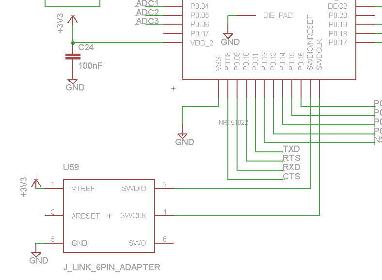
    With that said, programming the mcu is quite easy, as long as you design the PCB correctly! If you look at chapter 10 in the Reference Manual you will see that the chip supports Serial Wire Debugging, and only 2 signals are needed to program the device. If I'm not mistaken, your Ulink Pro debugger also supports SWD. When designing your PCB, simply connect the SWDCLK and SWDIO pins from the nRF51822 to a header, along with Vdd and GND. Having a 20-pin header for this is a bit overkill, so try perhaps to use an adapter instead. I'm using a 6-pin adapter, so my schematic looks like this:image description

    Notice that you don't need to connect the #RESET signal to the mcu.

    With this setup, you simply use Keil to program the chip the way you normally do

  • Can i use a ULINK2 to program the NRF?

Reply Children
No Data
Related