This post is older than 2 years and might not be relevant anymore
More Info: Consider searching for newer posts

UART communication between two boards

Hi,

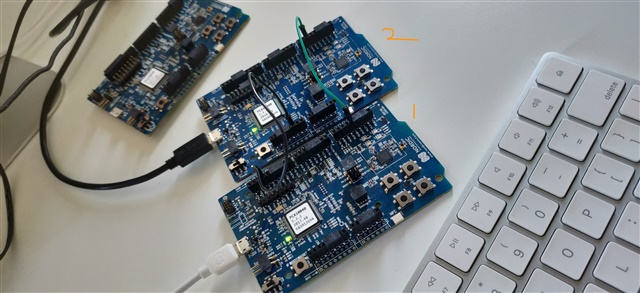
I am trying to establish UART communication between two nRF52 Dev boards. I flashed both of them with UART peripheral example from 15.2.0 SDK and connected TX,RX and GND pins.

Here, I encountered a weird issue where the two way communication(two terminals are recording the data when I enter data on any one terminal) is taking place with only one connection (TX from one board to RX on another / Connecting RX of both connectors) and nothing is being displayed on terminals when TX on both boards are connected. Can anyone explain this?

Thank you.

Parents
  • Hi.

    I'm not sure if I understand exactly what your setup looks like.

    You have only connected TX from one board to RX on another board, and are able to acheive two way communication? You also get two way communication connecting only RX from one board to RX on the other board?

    If you have two DK's (Board A and Board B),
    You should connect TX from board A to RX on board B and TX from board B to RX on board A.

    Could you provide some more information as well?
    Which SDK are you working with? nRF52 DK? Custom board? etc. 

    Best regards,
    Joakim

  • Hi,

    You have only connected TX from one board to RX on another board, and are able to acheive two way communication? You also get two way communication connecting only RX from one board to RX on the other board?

    Yes, this is what I was facing. I was on vacation and just returned today. So, didn't have much time working on this.

    If you have two DK's (Board A and Board B),
    You should connect TX from board A to RX on board B and TX from board B to RX on board A.

    This is what I have started with. Few weeks ago, it was working perfect with these connections but later it started to behave weirdly where the two way communication was occurring with only one connection. 

    I am working with 15.2.0 SDK, examples-> peripheral->uart. I didn't create any custom board. I am using pca10040.h file only. And yes, I am using nRF52 DK's with nRF52832.

    Thank you.

  • I tried it again today and the result was the same!! One connection (TX on Board1 to RX on Board2 / TX on Board2 to RX on Board1 / RX on both boards) is resulting in a two way communication!!

  • Hi.

    Thanks for the response.

    I haven't been able to reproduce this yet.
    Have you made any changes at all to the example, i.e changed the TX/RX pins?

    Regards,
    Joakim

Reply Children
  • Hi,

    I downloaded the stock SDK and and used the UART peripheral example directly. I haven't made any changes to the example.

    Thank you.

  • I'm afraid I haven't been able to reproduce this on my side.

    Maybe you could upload a picture of your setup with the nRF52-DK's?

    Also, you are using an unmodified version of the UART Hardware peripheral example?
    Located in <sdk_root>/examples/peripheral/uart

    Best regards,
    Joakim.

  • Hi Joakim,

    Sorry for the delay. This is the setup with the nRF52 DK's.

    I connected the grounds on both boards(black wire). Also connected TX on board 1 (P0.06) to RX on board 2 (P0.08) using green wire. 

    The code that I flashed on both boards is:

    /**
     * Copyright (c) 2014 - 2018, Nordic Semiconductor ASA
     *
     * All rights reserved.
     *
     * Redistribution and use in source and binary forms, with or without modification,
     * are permitted provided that the following conditions are met:
     *
     * 1. Redistributions of source code must retain the above copyright notice, this
     *    list of conditions and the following disclaimer.
     *
     * 2. Redistributions in binary form, except as embedded into a Nordic
     *    Semiconductor ASA integrated circuit in a product or a software update for
     *    such product, must reproduce the above copyright notice, this list of
     *    conditions and the following disclaimer in the documentation and/or other
     *    materials provided with the distribution.
     *
     * 3. Neither the name of Nordic Semiconductor ASA nor the names of its
     *    contributors may be used to endorse or promote products derived from this
     *    software without specific prior written permission.
     *
     * 4. This software, with or without modification, must only be used with a
     *    Nordic Semiconductor ASA integrated circuit.
     *
     * 5. Any software provided in binary form under this license must not be reverse
     *    engineered, decompiled, modified and/or disassembled.
     *
     * THIS SOFTWARE IS PROVIDED BY NORDIC SEMICONDUCTOR ASA "AS IS" AND ANY EXPRESS
     * OR IMPLIED WARRANTIES, INCLUDING, BUT NOT LIMITED TO, THE IMPLIED WARRANTIES
     * OF MERCHANTABILITY, NONINFRINGEMENT, AND FITNESS FOR A PARTICULAR PURPOSE ARE
     * DISCLAIMED. IN NO EVENT SHALL NORDIC SEMICONDUCTOR ASA OR CONTRIBUTORS BE
     * LIABLE FOR ANY DIRECT, INDIRECT, INCIDENTAL, SPECIAL, EXEMPLARY, OR
     * CONSEQUENTIAL DAMAGES (INCLUDING, BUT NOT LIMITED TO, PROCUREMENT OF SUBSTITUTE
     * GOODS OR SERVICES; LOSS OF USE, DATA, OR PROFITS; OR BUSINESS INTERRUPTION)
     * HOWEVER CAUSED AND ON ANY THEORY OF LIABILITY, WHETHER IN CONTRACT, STRICT
     * LIABILITY, OR TORT (INCLUDING NEGLIGENCE OR OTHERWISE) ARISING IN ANY WAY OUT
     * OF THE USE OF THIS SOFTWARE, EVEN IF ADVISED OF THE POSSIBILITY OF SUCH DAMAGE.
     *
     */
    /** @file
     * @defgroup uart_example_main main.c
     * @{
     * @ingroup uart_example
     * @brief UART Example Application main file.
     *
     * This file contains the source code for a sample application using UART.
     *
     */
    
    #include <stdbool.h>
    #include <stdint.h>
    #include <stdio.h>
    #include "app_uart.h"
    #include "app_error.h"
    #include "nrf_delay.h"
    #include "nrf.h"
    #include "bsp.h"
    #if defined (UART_PRESENT)
    #include "nrf_uart.h"
    #endif
    #if defined (UARTE_PRESENT)
    #include "nrf_uarte.h"
    #endif
    
    
    //#define ENABLE_LOOPBACK_TEST  /**< if defined, then this example will be a loopback test, which means that TX should be connected to RX to get data loopback. */
    
    #define MAX_TEST_DATA_BYTES     (15U)                /**< max number of test bytes to be used for tx and rx. */
    #define UART_TX_BUF_SIZE 256                         /**< UART TX buffer size. */
    #define UART_RX_BUF_SIZE 256                         /**< UART RX buffer size. */
    
    void uart_error_handle(app_uart_evt_t * p_event)
    {
        if (p_event->evt_type == APP_UART_COMMUNICATION_ERROR)
        {
            APP_ERROR_HANDLER(p_event->data.error_communication);
        }
        else if (p_event->evt_type == APP_UART_FIFO_ERROR)
        {
            APP_ERROR_HANDLER(p_event->data.error_code);
        }
    }
    
    
    #ifdef ENABLE_LOOPBACK_TEST
    /* Use flow control in loopback test. */
    #define UART_HWFC APP_UART_FLOW_CONTROL_ENABLED
    
    /** @brief Function for setting the @ref ERROR_PIN high, and then enter an infinite loop.
     */
    static void show_error(void)
    {
    
        bsp_board_leds_on();
        while (true)
        {
            // Do nothing.
        }
    }
    
    
    /** @brief Function for testing UART loop back.
     *  @details Transmitts one character at a time to check if the data received from the loopback is same as the transmitted data.
     *  @note  @ref TX_PIN_NUMBER must be connected to @ref RX_PIN_NUMBER)
     */
    static void uart_loopback_test()
    {
        uint8_t * tx_data = (uint8_t *)("\r\nLOOPBACK_TEST\r\n");
        uint8_t   rx_data;
    
        // Start sending one byte and see if you get the same
        for (uint32_t i = 0; i < MAX_TEST_DATA_BYTES; i++)
        {
            uint32_t err_code;
            while (app_uart_put(tx_data[i]) != NRF_SUCCESS);
    
            nrf_delay_ms(10);
            err_code = app_uart_get(&rx_data);
    
            if ((rx_data != tx_data[i]) || (err_code != NRF_SUCCESS))
            {
                show_error();
            }
        }
        return;
    }
    #else
    /* When UART is used for communication with the host do not use flow control.*/
    #define UART_HWFC APP_UART_FLOW_CONTROL_DISABLED
    #endif
    
    
    /**
     * @brief Function for main application entry.
     */
    int main(void)
    {
        uint32_t err_code;
    
        bsp_board_init(BSP_INIT_LEDS);
    
        const app_uart_comm_params_t comm_params =
          {
              RX_PIN_NUMBER,
              TX_PIN_NUMBER,
              RTS_PIN_NUMBER,
              CTS_PIN_NUMBER,
              UART_HWFC,
              false,
    #if defined (UART_PRESENT)
              NRF_UART_BAUDRATE_115200
    #else
              NRF_UARTE_BAUDRATE_115200
    #endif
          };
    
        APP_UART_FIFO_INIT(&comm_params,
                             UART_RX_BUF_SIZE,
                             UART_TX_BUF_SIZE,
                             uart_error_handle,
                             APP_IRQ_PRIORITY_LOWEST,
                             err_code);
    
        APP_ERROR_CHECK(err_code);
    
    #ifndef ENABLE_LOOPBACK_TEST
        printf("\r\nUART example started.\r\n");
    
        while (true)
        {
            uint8_t cr;
            while (app_uart_get(&cr) != NRF_SUCCESS);
            while (app_uart_put(cr) != NRF_SUCCESS);
    
            if (cr == 'q' || cr == 'Q')
            {
                while (app_uart_get(&cr) != NRF_SUCCESS);
                printf(" \r\nValue: %d\r\n", cr);
            }
        }
    #else
    
        // This part of the example is just for testing the loopback .
        while (true)
        {
            uart_loopback_test();
        }
    #endif
    }
    
    
    /** @} */
    

    After flashing, I opened putty emulator for UART ports on both boards. When I send characters from board 1; they are displayed on terminal for board 2. 

    Next, when I send characters from board 2, they are being displayed on terminal for board 1 when I didn't connect board 2 TX to board1 RX.

    What might be the reason?

    Thank you.

Related