Beware that this post is related to an SDK in maintenance mode
More Info: Consider nRF Connect SDK for new designs
This post is older than 2 years and might not be relevant anymore
More Info: Consider searching for newer posts

Reading WS2812b leftover data through I2S

Hello there,

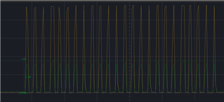
I am currently trying to read the leftover WS2812b LED strip data which was sent using a single channel I2S. The data sent from the board (through I2S) looks like this:

with around 34 mV for high and around 2~6 mV on low. I decided not to send FFF, but 888 instead.

I am aiming to calculate the length of the LED strip. Each LED chip will read the first 24 bits of the data, cascade (discard) it, then pass it to the next one. Therefore, the strategy is to get the data after being cascaded by the last chip and calculate the length of it (which later will be divided by 24 to see how many are left).

The question is: How will I be able to read those data? I tried reading as usual (set a buffer for the i2s, start it, listen for it (delay), stop it, then check its buffer), but I got my buffer filled with all FFF instead. and a thing is that... when I tried to read anything from the pin, although I am not sending any data (the LED strip is not powered on, but connected to other's ground), there will be data, which should not happen. I assigned pin 22, 23, 24, 25 to be the i2s input pin (which will be assigned and unassigned when used or unused), and they are configured as follows:

nrf_gpio_cfg_sense_input(DIN1_PIN, NRF_GPIO_PIN_PULLDOWN, NRF_GPIO_PIN_SENSE_HIGH);

Thank you in advance.

Parents
  • Hi Einar,

    Sorry, please disregard 34 mV and 2~6 mV, it's wrong, it should be 2.79 V for High and -15.9 mV (or 0 V) for Low. This is the data signal created on WS2812B's Data out.

    I connected the strip directly to the board's VDD to power it on, P0.11 for Data, and ground. I did not use any level converter (I know that I'm suggested to supply 5v and use a level converter, but 3.3 V is able to turn the LED on so, I'm trying it).

    When there is no data being transferred through the WS2812b, the voltage of the DOUT is around -0.8 mV ~ -78.92 mV. At this state, if I call the board to read any data, by using

    i2s_config_init(DIN2_PIN, 17);

    where DIN2_PIN is defined by

    #define DIN2_PIN 23

    , followed by

    i2s_start();
    nrf_delay_us(I2S_DETECTION);
    
    for (i = 1; i < I2S_BUFFER_SIZE; i++) {
    	if (I2SRxBuffer[i] != 0 || I2SRxBuffer[i] != -1) {
    		printf("isi: %x\r\n", I2SRxBuffer[i]);
    		printf("as: %d\r\n", I2SRxBuffer[i]);
    		if (I2SRxBuffer[i] > 0x11111110) {
    			lengthz++;
    		}
    	}
    }
    
    i2s_stop();

    , I2SRxBuffer[i] will always print ffffffff.

  • Hi,

    OK. The logical levels for the nRF are supposed to be above 0.7 * Vdd for high and below 0.3 * Vdd (but > 0 V) for low. However, I would not expect that the logical levels are OK for the nRF, and the low negative voltage for logical '0' should be ok. But I would not do it like this in an actual end product.

    I do not have any idea if the voltages are acceptable to the WS2812b, though. It is out of spec after all (according to the datasheet it should be between +3.5 and +5.3). Can you show us logic analyzer plots of the data out of the WS2812b? Is it all FF's there as well? If so then I would try using a level shifter and supplying the WS2812b with a voltage within spec before digging any further.

    By the way, are you basing your endeavors on this blog post?

  • Yes, that is right. Now that you mentioned about it, I checked and confirmed: you're right, it is not anywhere above 3 V. so... I suppose I am stuck with 5V and level converters.. okay..

    That being said, do I need to regulate the signal down back to 3 V (step down) using level converter before connecting it to other board?

  • You need level shifters on signals going both ways in order to respect the limitations of both devices. It is described in the blog you are using as far as I can see.

  • Alright, I get that.

    Okay, I connected board A -> level shifter A -> LED's Data in. Then, LED Data Out (the same strip, uncut) -> Level Shifter B (Hi) -> Level Shifter B (Low) -> Board B. I used oscilloscope and found out that the data is all the same, but with a lower voltage: (max) 214.84 mV. Is this the expected behavior?

    The yellow probe is connected exactly after the DOUT of WS2812 and green probe is connected at Level Shifter B's LOW Output (please refer to the diagram below).

    No matter if I use 1 nor 2 level shifters, they will result the same. output at this voltage.

    I connected the level shifters this way:

    Notes:

    * Those are NRF52DK, PCA10040, not Arduinos.

    * The extra blue cables from the LEDs means they are connected to ground

    * The left board (Board A)'s output is set at P0.11 ~ P 0.14 (I need 4 of them)

    * The right board (Board B)'s input is set at P 0.22 ~ P 0.25 (I need 4 of them)

  • Oh, sorry, I didn' realize this until last night, before I go to sleep

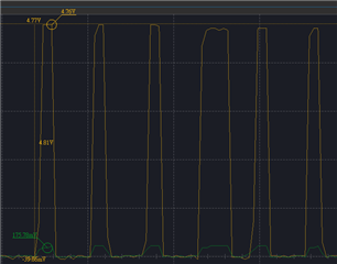
    I set the oscilloscope probe wrong. This is the correct data:

    and yes, i still receive ff's on the i2s input

  • Hi,

    I am just summing up the basics here:

    • Logic '0' for the WS2812 is transmitted from nRF SPI peripheral as 0b0001 = 0x1
    • Logic '1' for the WS2812 is transmitted from the nRF SPI peripheral as 0b1110 = 0xE
    • And the other way around for receiving.

    Are you sending a string of 0x1 and 0xE's from the I2S peripheral as you should, and this works properly so that the (color and intensity is set as expected)? If no, then you should look at how you write data first. I am having a bit of problems reading the oscilloscope plots, but it does seem like the bit sequence in the last plot is 00010000 00000000 00010000 (a short high level after the rising edge is '1' and a long high level is '0'). Which data did you shift in? Is it the same? If it is, then so far so good, and the problem is only with reading the data back from the nRF.

    Reading the data from the nRF using the I2S peripheral will be more difficult (if possible). I2S assumes the data to be synchronous, but there is no relationship between the I2S clock and the data out of the WS2812 in this case. And even if we are lucky, how steep are the rising and falling edges? If the nRF samples at a bad time, it might read data which is in the undefined regions. I think the conclusion is that it is difficult to achieve this in practice using the I2S peripheral.

    A better approach could be to oversample the signal using another approach. I think the only viable approach on the nRF is to oversample the signal by reading the GPIO pin at a high frequency, and then analyzing it, doing edge detection to decode the signal. Unfortunately, the nRF does not have a generic way to sample GPIO pins and storing it using DMA, so you have to do it in SW. That might be OK though, as long as the speed is not too high and the nRF does not do much else.

Reply
  • Hi,

    I am just summing up the basics here:

    • Logic '0' for the WS2812 is transmitted from nRF SPI peripheral as 0b0001 = 0x1
    • Logic '1' for the WS2812 is transmitted from the nRF SPI peripheral as 0b1110 = 0xE
    • And the other way around for receiving.

    Are you sending a string of 0x1 and 0xE's from the I2S peripheral as you should, and this works properly so that the (color and intensity is set as expected)? If no, then you should look at how you write data first. I am having a bit of problems reading the oscilloscope plots, but it does seem like the bit sequence in the last plot is 00010000 00000000 00010000 (a short high level after the rising edge is '1' and a long high level is '0'). Which data did you shift in? Is it the same? If it is, then so far so good, and the problem is only with reading the data back from the nRF.

    Reading the data from the nRF using the I2S peripheral will be more difficult (if possible). I2S assumes the data to be synchronous, but there is no relationship between the I2S clock and the data out of the WS2812 in this case. And even if we are lucky, how steep are the rising and falling edges? If the nRF samples at a bad time, it might read data which is in the undefined regions. I think the conclusion is that it is difficult to achieve this in practice using the I2S peripheral.

    A better approach could be to oversample the signal using another approach. I think the only viable approach on the nRF is to oversample the signal by reading the GPIO pin at a high frequency, and then analyzing it, doing edge detection to decode the signal. Unfortunately, the nRF does not have a generic way to sample GPIO pins and storing it using DMA, so you have to do it in SW. That might be OK though, as long as the speed is not too high and the nRF does not do much else.

Children
  • Hi,

    That is right, the data I shifted in is the same on both input and output (it's actually 00010000 00000000 01010000).

    Ah.. okay... I did not remember about timing, especially when both are not connected directly.

    During this time (receiving data time), the nRF does not have to do anything else. Therefore, I think it may be safe to do GPIO reading for several ms, right? That being said, is 1.78 V safe for nRF52's GPIO Input? (Yes, as I checked the documentation). And what about the current? my multimeter seems like did not read any current from the Data Out of WS2812b (or there should not be?)

    As well, will nRF52 be able to detect the voltage change, between 0.x mV and 1.8 V on the GPIO output? I was thinking to reserve a time for nRF52 to count (in us (microsecond)), then once it detected signal change, read the second one (remember both time). Then, analyze it and decide if it's a 1 or 0 and so on. Do you think this will be a good idea?

    Thank you.

  • Hi,

    Regarding current the inputs have a high impedance, so you will see very little current on the data line. That is correct and expected.

    I assume you want to know if the nRF can detect voltage change on a GPIO input? That is a good idea. You can combine a comparator and timer with PPI and measure the time between the edges of the data signal by triggering timer capture registers from the comparator. That will be handled mostly in HW, but you would need to generate a interrupt for every bit and read the timer registers before the start of the next bit, so you will still have to handle the interrupts in a timely manner.

  • Hi,

    Alright, I will try that. Or do you have other idea you would like to suggest?

    And is there any other things that I may need to notice?

    I noticed from the Documentation Library that I will need to use the Analog Pins (AIN0 ~ AIN7). Therefore, I suppose Digital Pins will not be able to do it? Assuming I'm using a comparator

    Thank you

  • Hi,

    Yes, the comparator (and the other analog peripherals) can only be used with the 8 analog pins (see pinout in Product spec). Nothing else comes to mind at this point.

  • Hi,

    Oh, alright.

    By the way, I got a suggestion: keep using i2s to read the data. While the clock may not be synchronized, we create a Clock Phase Locking, setting an interrupt on the other board; which when triggered, will start the i2s over there and hopefully will be able to read and understand the data. What would you say about this?

Related