Beware that this post is related to an SDK in maintenance mode
More Info: Consider nRF Connect SDK for new designs
This post is older than 2 years and might not be relevant anymore
More Info: Consider searching for newer posts

Reading WS2812b leftover data through I2S

Hello there,

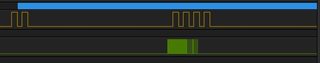
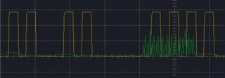
I am currently trying to read the leftover WS2812b LED strip data which was sent using a single channel I2S. The data sent from the board (through I2S) looks like this:

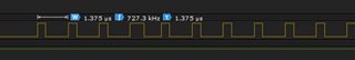
with around 34 mV for high and around 2~6 mV on low. I decided not to send FFF, but 888 instead.

I am aiming to calculate the length of the LED strip. Each LED chip will read the first 24 bits of the data, cascade (discard) it, then pass it to the next one. Therefore, the strategy is to get the data after being cascaded by the last chip and calculate the length of it (which later will be divided by 24 to see how many are left).

The question is: How will I be able to read those data? I tried reading as usual (set a buffer for the i2s, start it, listen for it (delay), stop it, then check its buffer), but I got my buffer filled with all FFF instead. and a thing is that... when I tried to read anything from the pin, although I am not sending any data (the LED strip is not powered on, but connected to other's ground), there will be data, which should not happen. I assigned pin 22, 23, 24, 25 to be the i2s input pin (which will be assigned and unassigned when used or unused), and they are configured as follows:

nrf_gpio_cfg_sense_input(DIN1_PIN, NRF_GPIO_PIN_PULLDOWN, NRF_GPIO_PIN_SENSE_HIGH);

Thank you in advance.

Parents
  • Hi Einar,

    Sorry, please disregard 34 mV and 2~6 mV, it's wrong, it should be 2.79 V for High and -15.9 mV (or 0 V) for Low. This is the data signal created on WS2812B's Data out.

    I connected the strip directly to the board's VDD to power it on, P0.11 for Data, and ground. I did not use any level converter (I know that I'm suggested to supply 5v and use a level converter, but 3.3 V is able to turn the LED on so, I'm trying it).

    When there is no data being transferred through the WS2812b, the voltage of the DOUT is around -0.8 mV ~ -78.92 mV. At this state, if I call the board to read any data, by using

    i2s_config_init(DIN2_PIN, 17);

    where DIN2_PIN is defined by

    #define DIN2_PIN 23

    , followed by

    i2s_start();
    nrf_delay_us(I2S_DETECTION);
    
    for (i = 1; i < I2S_BUFFER_SIZE; i++) {
    	if (I2SRxBuffer[i] != 0 || I2SRxBuffer[i] != -1) {
    		printf("isi: %x\r\n", I2SRxBuffer[i]);
    		printf("as: %d\r\n", I2SRxBuffer[i]);
    		if (I2SRxBuffer[i] > 0x11111110) {
    			lengthz++;
    		}
    	}
    }
    
    i2s_stop();

    , I2SRxBuffer[i] will always print ffffffff.

  • Hi,

    OK. The logical levels for the nRF are supposed to be above 0.7 * Vdd for high and below 0.3 * Vdd (but > 0 V) for low. However, I would not expect that the logical levels are OK for the nRF, and the low negative voltage for logical '0' should be ok. But I would not do it like this in an actual end product.

    I do not have any idea if the voltages are acceptable to the WS2812b, though. It is out of spec after all (according to the datasheet it should be between +3.5 and +5.3). Can you show us logic analyzer plots of the data out of the WS2812b? Is it all FF's there as well? If so then I would try using a level shifter and supplying the WS2812b with a voltage within spec before digging any further.

    By the way, are you basing your endeavors on this blog post?

  • Is the pin floating? If so, then you cannot really measure it. Can you try to connect it to ground / VSS/ 0 V and see if you still get the unexpected interrupts?

  • Hello,

    No, the pin is not floating. It is connected to the last WS2812B (after being converted to a lower voltage).

    Here are the screenshot of how my logic analyzer and oscilloscope say about the signal:

    Logic Analyzer:

    Oscilloscope:

    The green lines are the signal coming from the last LED; and the yellow lines are the output from the COMP handler.

    On the oscilloscope, the amount of voltage on the green line (which may lead to the false trigger) are 214.84mV, 58.59mV, 136.72mV, and 58.59mV. whereas the rest, low voltages such as 19mV does not trigger the handler (which is expected)

  • Hi, I see. Have you attempted to find the source of the noise? Do you still see it if you disconnect the WS2812b data out from the nRF GPIO (COMP) input and measure on the WS2812b data pin? If yes, then the COMP behaves as it should, but there is noise form WS2812b for some reason. Depending on the noise, perhaps you can low pass filter it (for instance using a simple RC-filter).

  • Hi,

    There are 3 cases I have observed:

    1. If I disconnect (or connect it but did not power the WS2812b), then the COMP handler will be triggered all the time. Seems like 566.41 mV triggers the handler. (It's not accepted, right?) Shorting it to Ground makes it zero, handler not called.

    2. If I power the WS2812b on, without sending any data, then the handler will not be called. The voltage is around 0.0 mV, which is accepted.

    3. As soon as I send a data (I asked it to turn 11 lights on (extra 1)), the activity from above happens.

    I connected my oscilloscope's probe to the end of WS2812B Data out and figured out that there are some sudden (unwanted?) spikes coming out from it. I think this what somehow triggers the handler (the voltage there is 214.84 mV max though).

    I will try to low pass filter it.

    Aside, why does the noises triggers the COMP's handler? They are set to trigger at 1.1 V and 1.3 V, not 566.41 mV. Is there any special calculation for setting the trigger?

  • Hi,

    1. In this case the GPIO input on the nRF is floating (doesn't have any properly defined voltage), so anything could happen. That is expected. You should never have floating input pins. The 566.41 mV you measure cannot be trusted, since the pin is floating. You will probably get very different measurements depending on what instrument you use to measure.

    2. OK, that is also expected.

    3. This is caused by noise from the WS2812b, which you have to handle in some way. The most obvious fix is to low pass filter the data signal.

Reply
  • Hi,

    1. In this case the GPIO input on the nRF is floating (doesn't have any properly defined voltage), so anything could happen. That is expected. You should never have floating input pins. The 566.41 mV you measure cannot be trusted, since the pin is floating. You will probably get very different measurements depending on what instrument you use to measure.

    2. OK, that is also expected.

    3. This is caused by noise from the WS2812b, which you have to handle in some way. The most obvious fix is to low pass filter the data signal.

Children
  • A problem is that I do not understand how the COMP works. I set it to call the handler every time the voltage changes (yes, I need to detect when it changes to 0 and when it changes to 1).

    Here is my handler:

    static void comp_event_handler(nrf_comp_event_t event) {
    	if (event == NRF_COMP_EVENT_CROSS) {
    		nrf_gpio_pin_set(DEBUG_PIN);
    		///nrf_delay_us(5);
    		nrf_gpio_pin_clear(DEBUG_PIN);
    	}
    }

    and here is my COMP initialization:

    static void comp_init(void) {
    	#define lo_volt 0.59 // The voltage indicating "0"
    	#define hi_volt 1.4 // The voltage indicating "1"
    	double Ref_voltage = 2.4;
    	
    	double ThresholdLo = (Ref_voltage / 1024) * lo_volt;
    	double ThresholdHi = (Ref_voltage / 1024) * hi_volt;
    	
    	uint32_t err_code = NRF_SUCCESS;
    	
    	nrf_drv_comp_config_t comp_config = NRF_DRV_COMP_DEFAULT_CONFIG(NRF_COMP_INPUT_0);
    	comp_config.isource = NRF_COMP_ISOURCE_Ien5uA;
    	// Configure threshold voltages.
    	comp_config.threshold.th_down = VOLTAGE_THRESHOLD_TO_INT(ThresholdLo, Ref_voltage);
        comp_config.threshold.th_up   = VOLTAGE_THRESHOLD_TO_INT(ThresholdHi, Ref_voltage);
    	comp_config.isource = NRF_COMP_ISOURCE_Off;
        comp_config.main_mode = NRF_COMP_MAIN_MODE_SE;
    	
    	err_code = nrf_drv_comp_init(&comp_config, comp_event_handler);
    	
    	APP_ERROR_CHECK(err_code);
    	nrf_drv_comp_start(NRF_DRV_COMP_EVT_EN_CROSS_MASK, NULL);
    }

    *I changed the definition of the threshold because I refer to another post's which seem to be working.

    I figured out that the electricity of 1.2 V, 1.4 V or max 1.8 V indicates a 1, while the electricity of 58.59 mV indicates 0, as captured using my oscilloscope:

    Using this configuration, I did not receive the output as I expected. Instead, the handler seem to be called every time a noise (as low as 39 mV) is detected (yes, the output of this LED string is really noisy, although there is no more data to be sent and the light is static).

    Another problem is when I sent a bunch of data, the COMP seems not calling the handler as much as the data received. Instead, it only trigger once.

    The yellow line is the signal created by the handler, and the purple line is the signal from the LED string after being stepped-down.

  • Oh right, about the low pass filter. I am still not sure about this, but what I have found on Google are saying about the current being AC. Or can I still continue with it?

  • Hi,

    I assume you are no longer testing with a floating input? If chat can occur of some reason in practice, then you should add a pull resistor on the data line so that you know it can never be floating.

    Winz said:
    I figured out that the electricity of 1.2 V, 1.4 V or max 1.8 V indicates a 1, while the electricity of 58.59 mV indicates 0, as captured using my oscilloscope:

    The plots are too small to read. Can you edit the post and upload full-size versions? What do you mean by 1.2, 1.4 or max 1.8 V. Roughly what is the logic '1' and logic '0' levels of the input signal on the COMP? Does it show in the plot? Essentially you just need to set the levels within what you will always see in practice, and generate events on crossings.

    Another thing we have not discussed, but which is worth mentioning, is that you can simplify this quite a bit by just selecting a level shifter which will provide valid logic levels for the nRF. Then you would not have to use the COMP at all, but could just use normal GPIO pins.

  • level shifter which will provide valid logic levels for the nRF

    Hmm, would you recommend one for me? I am using this one, which uses this. Will this provide valid logic levels for the nRF?

    could just use normal GPIO pins

    Hmm, are you referring to GPIOTE? Is GPIOTE interrupt fast to catch the data (as fast as i2s)?

    I have tried the example "pin_change_int", which uses GPIOTE, and here is the result:

    The yellow line is probed right to the pin which has been registered as the input to be monitored.

    The green line is probed right to the pin which has been registered as the output.

  • Hi,

    Winz said:
    Hmm, would you recommend one for me? I am using this one, which uses this. Will this provide valid logic levels for the nRF?

    I don't have any particular recommendations, it is up to you.

    Winz said:
    Hmm, are you referring to GPIOTE? Is GPIOTE interrupt fast to catch the data (as fast as i2s)?

    I am not entirely sure about the questions. GPIOTE is essentially just a way to generate events on inputs or control the outputs using tasks, which is a concept used in nRF devices. Then you can hook it up to for instance a timer using PPI to measure the duration of a pulse. That could make sense in this case.

    Winz said:

    The yellow line is probed right to the pin which has been registered as the input to be monitored.

    The green line is probed right to the pin which has been registered as the output.

    I am not sure what I am looking at The yellow light looks like noise?

Related