This post is older than 2 years and might not be relevant anymore
More Info: Consider searching for newer posts

nrf52832 spi (PSEL.SCK)

I use nrf52832 SPIM, and I want there are gaps between every 8clock, so I set  NRF_SPIM0->TXD.MAXCNT = 1; NRF_SPIM0->RXD.MAXCNT = 1; ,But there is alway more clock than I want,(I want to write 8clock, but there are 16clock), then the nordic engineer tell me to use PPI(setup_workaround_for_ftpan_58). now, the SPI work well , but I find another question, I must put P0.30 as output pin,and there is gaps between every 8clock, If I didn't config P0.30, there is not gaps between every 8clock, just like bellow,is that right?

I asked the quetion in https://devzone.nordicsemi.com/f/nordic-q-a/40522/nrf52832-spi-psel-sck-timing, but there is no reply.There are more details in the link.

Parents
  • Try:

    spi_master_init();
    nrf_gpio_cfg_output(30); // if pin30 is not set output and set1/clear0,spi sck is not right
    nrf_gpio_pin_clear(30);
    //last_valid_cmd[0] = 0;

    and see if the issue still appears.

    You can download our SDK from here

    Best regards

    Jared  

  • there is the same problem in spi sck when I use the nRF5_SDK_15.0.0_a53641a, I  use the project in \nRF5_SDK_15.0.0_a53641a\examples\peripheral\spi\pca10040\blank\arm5_no_packs, and alternate three files: main.c, nrf_drv_spi.c, nrf_drv_spi.h. main.c is just like below:

    spi_test.rar

    #include "nrf_drv_spi.h"
    
    volatile uint8_t tx_buf[10];
    volatile bool transfer_in_progress = 0;
     
    /**
     * @brief Work-around for transmitting 1 byte with SPIM.
     * @param spim: The SPIM instance that is in use.
     * @param ppi_channel: An unused PPI channel that will be used by the workaround.
     * @param gpiote_channel: An unused GPIOTE channel that will be used by the workaround.
     * @warning Must not be used when transmitting multiple bytes.
     * @warning After this workaround is used, the user must reset the PPI channel and the GPIOTE channel before attempting to transmit multiple bytes.
     */
    void setup_workaround_for_ftpan_58(uint32_t ppi_channel, uint32_t gpiote_channel)
    {
        // Create an event when SCK toggles.
        NRF_GPIOTE->CONFIG[gpiote_channel] = (GPIOTE_CONFIG_MODE_Event <<GPIOTE_CONFIG_MODE_Pos) | 
            (NRF_SPIM0->PSELSCK << GPIOTE_CONFIG_PSEL_Pos) | 
            (GPIOTE_CONFIG_POLARITY_Toggle << GPIOTE_CONFIG_POLARITY_Pos);
    
        // Stop the spim instance when SCK toggles.
        NRF_PPI->CH[ppi_channel].EEP = (uint32_t)&NRF_GPIOTE->EVENTS_IN[gpiote_channel];
        NRF_PPI->CH[ppi_channel].TEP = (uint32_t)&NRF_SPIM0->TASKS_STOP;
        NRF_PPI->CHENSET = 1U << ppi_channel;
    
        // The spim instance cannot be stopped mid-byte, so it will finish
        // transmitting the first byte and then stop. Effectively ensuring
        // that only 1 byte is transmitted.
    }
    
    void spi_master_init(void)
    {
    	// Configure GPIO pins used for pselsck, pselmosi, pselmiso and pselss for SPI1
        nrf_gpio_cfg_output(SPI_PSELSCK1);
        nrf_gpio_cfg_output(SPI_PSELMOSI1);
        nrf_gpio_cfg_input(SPI_PSELMISO1, NRF_GPIO_PIN_PULLDOWN);
        nrf_gpio_cfg_output(SPI_PSELSS1);
    
        // Configure pins, frequency and mode 
        NRF_SPIM0->PSELSCK  = SPI_PSELSCK1;
        NRF_SPIM0->PSELMOSI = SPI_PSELMOSI1;
        NRF_SPIM0->PSELMISO = SPI_PSELMISO1;
        nrf_gpio_pin_set(SPI_PSELSS1);         // disable Set slave select (inactive high) 
    
        NRF_SPIM0->FREQUENCY = (uint32_t) ( 0x02000000UL << (uint32_t)Freq_8Mbps);
        NRF_SPIM0->CONFIG = (SPI_CONFIG_CPHA_Leading << SPI_CONFIG_CPHA_Pos) | 
        (SPI_CONFIG_CPOL_ActiveHigh << SPI_CONFIG_CPOL_Pos) | 
        (SPI_CONFIG_ORDER_MsbFirst << SPI_CONFIG_ORDER_Pos);
        NRF_SPIM0->ENABLE = (SPIM_ENABLE_ENABLE_Enabled << SPIM_ENABLE_ENABLE_Pos);
            
        NRF_SPIM0->INTENSET = 0;
        nrf_ppi_channel_t ppi_channel1;
        setup_workaround_for_ftpan_58(ppi_channel1,1);    
    }
    
    
    static void spi_master_rx2(const uint8_t *head, uint8_t head_size, uint8_t data_size, uint8_t *rx_data)
    {
        uint8_t i = 0;
        
        for(i=0;i<head_size;i++)
        {
           tx_buf[i] =  *head++;
        }
        for(i=head_size;i<(head_size+data_size);i++)
        {
           tx_buf[i] =  0;
        }
       
        nrf_gpio_pin_clear(SPI_PSELSS1);
        
        NRF_SPIM0->EVENTS_END = 0U;
    	NRF_SPIM0->EVENTS_STOPPED = 0U;
        
        NRF_SPIM0->TXD.MAXCNT = 1;  
        NRF_SPIM0->RXD.MAXCNT = 1;     
        NRF_SPIM0->TXD.LIST = 0;
        NRF_SPIM0->RXD.LIST = 0;
        NRF_SPIM0->SHORTS = SPIM_SHORTS_END_START_Msk;
        
        NRF_SPIM0->TXD.PTR = (uint32_t)tx_buf;
        NRF_SPIM0->TASKS_START = 1U;
        
        for(i=1;i<head_size;i++)
        {
            NRF_SPIM0->TXD.PTR = (uint32_t)tx_buf+i;
            
            while (NRF_SPIM0->EVENTS_END == 0U);
            NRF_SPIM0->EVENTS_END = 0U;
        } 
        NRF_SPIM0->RXD.PTR = (uint32_t)rx_data++;
        
        for(i=head_size;i<(head_size+data_size);i++)
        {
            NRF_SPIM0->TXD.PTR = (uint32_t)tx_buf+i;
            while (NRF_SPIM0->EVENTS_END == 0U);
            NRF_SPIM0->EVENTS_END = 0U;
            NRF_SPIM0->RXD.PTR = (uint32_t)rx_data++;  
        }         
        
        while (NRF_SPIM0->EVENTS_STARTED == 0U);
        NRF_SPIM0->EVENTS_STARTED = 0U;
        NRF_SPIM0->SHORTS = 0;
        
        while (NRF_SPIM0->EVENTS_END == 0U);    
        NRF_SPIM0->EVENTS_END = 0U; 
        
        nrf_gpio_pin_set(SPI_PSELSS1);
        NRF_SPIM0->TASKS_STOP = 1U;    
    }
    
    static void spi_master_tx2(const uint8_t *head, uint8_t head_size, uint8_t data_size, const uint8_t *tx_data)
    {
        uint8_t i = 0;
        
        for(i=0;i<head_size;i++)
        {
           tx_buf[i] =  *head++;
        }
        for(i=head_size;i<(head_size+data_size);i++)
        {
           tx_buf[i] =  *tx_data++;
        }   
        
        nrf_gpio_pin_clear(SPI_PSELSS1);
        
        NRF_SPIM0->EVENTS_ENDTX = 0U;
    	NRF_SPIM0->EVENTS_STOPPED = 0U;    
        NRF_SPIM0->TXD.MAXCNT = 1;
        NRF_SPIM0->SHORTS = SPIM_SHORTS_END_START_Msk;
        
        NRF_SPIM0->TXD.PTR = (uint32_t)tx_buf;
        NRF_SPIM0->TASKS_START = 1U;
        
        for(i=1;i<(head_size+data_size);i++)
        {
            NRF_SPIM0->TXD.PTR = (uint32_t)tx_buf+i;
            while (NRF_SPIM0->EVENTS_ENDTX == 0U);
            NRF_SPIM0->EVENTS_ENDTX = 0U;
        }         
        
        while (NRF_SPIM0->EVENTS_STARTED == 0U);
        NRF_SPIM0->EVENTS_STARTED = 0U;
        NRF_SPIM0->SHORTS = 0;
        
        while (NRF_SPIM0->EVENTS_ENDTX == 0U);    
        NRF_SPIM0->EVENTS_ENDTX = 0U;
       
        nrf_gpio_pin_set(SPI_PSELSS1);    
    }
    
    void mcu_asic_regs_read(uint16_t addr, uint8_t length, uint8_t *dat)
    {
        uint8_t head[4];
        head[0] = (0xC0|(((uint8_t)(addr>>8))&0x0F));      // wr+add[11:8]
        head[1] = addr;
        head[2] = length;
        
        spi_master_rx2(head, 3, length, dat);
    }
    
    void mcu_asic_regs_write(uint16_t addr, uint8_t length, const uint8_t *dat)
    {
        uint8_t head[3];
        head[0] = (0xD0|(((uint8_t)(addr>>8))&0x0F));      // wr+add[11:8]
        head[1] = addr;
        head[2] = length;
        
        spi_master_tx2(head, 3, length, dat);
    }
    
     void mcu_asic_reg_write(uint16_t addr, const uint8_t dat)
    {
        uint8_t i = 0;
        
        tx_buf[0] = (0xF0|(((uint8_t)(addr>>8))&0x0F));
        tx_buf[1] = addr;
        tx_buf[2] = dat;    
        
        nrf_gpio_pin_clear(SPI_PSELSS1);
        
        NRF_SPIM0->EVENTS_ENDTX = 0U;
    	NRF_SPIM0->EVENTS_STOPPED = 0U;    
        NRF_SPIM0->TXD.MAXCNT = 1;
        NRF_SPIM0->SHORTS = SPIM_SHORTS_END_START_Msk;
        
        NRF_SPIM0->TXD.PTR = (uint32_t)tx_buf;
        NRF_SPIM0->TASKS_START = 1U;
        
        for(i=1;i<3;i++)
        {
            NRF_SPIM0->TXD.PTR = (uint32_t)tx_buf+i;
            while (NRF_SPIM0->EVENTS_ENDTX == 0U);
            NRF_SPIM0->EVENTS_ENDTX = 0U;
        }         
        
        while (NRF_SPIM0->EVENTS_STARTED == 0U);
        NRF_SPIM0->EVENTS_STARTED = 0U;
        NRF_SPIM0->SHORTS = 0;
        
        while (NRF_SPIM0->EVENTS_ENDTX == 0U);    
        NRF_SPIM0->EVENTS_ENDTX = 0U;
       
        nrf_gpio_pin_set(SPI_PSELSS1);        
    }
    
    void mcu_asic_img_read(uint32_t addr, uint8_t length, uint8_t *dat)
    {
        uint8_t head[5];
        head[0] = (0x80|(((uint8_t)(addr>>16))&0x01));      // wr+add[11:8]
        head[1] = (addr>>8);
        head[2] = addr;
        
        head[3] = 0;
        head[4] = length;
        
        spi_master_rx2(head, 5, length, dat);
    }
    

    7215.nrf_drv_spi.h

    /**
     * Copyright (c) 2015 - 2018, Nordic Semiconductor ASA
     * 
     * All rights reserved.
     * 
     * Redistribution and use in source and binary forms, with or without modification,
     * are permitted provided that the following conditions are met:
     * 
     * 1. Redistributions of source code must retain the above copyright notice, this
     *    list of conditions and the following disclaimer.
     * 
     * 2. Redistributions in binary form, except as embedded into a Nordic
     *    Semiconductor ASA integrated circuit in a product or a software update for
     *    such product, must reproduce the above copyright notice, this list of
     *    conditions and the following disclaimer in the documentation and/or other
     *    materials provided with the distribution.
     * 
     * 3. Neither the name of Nordic Semiconductor ASA nor the names of its
     *    contributors may be used to endorse or promote products derived from this
     *    software without specific prior written permission.
     * 
     * 4. This software, with or without modification, must only be used with a
     *    Nordic Semiconductor ASA integrated circuit.
     * 
     * 5. Any software provided in binary form under this license must not be reverse
     *    engineered, decompiled, modified and/or disassembled.
     * 
     * THIS SOFTWARE IS PROVIDED BY NORDIC SEMICONDUCTOR ASA "AS IS" AND ANY EXPRESS
     * OR IMPLIED WARRANTIES, INCLUDING, BUT NOT LIMITED TO, THE IMPLIED WARRANTIES
     * OF MERCHANTABILITY, NONINFRINGEMENT, AND FITNESS FOR A PARTICULAR PURPOSE ARE
     * DISCLAIMED. IN NO EVENT SHALL NORDIC SEMICONDUCTOR ASA OR CONTRIBUTORS BE
     * LIABLE FOR ANY DIRECT, INDIRECT, INCIDENTAL, SPECIAL, EXEMPLARY, OR
     * CONSEQUENTIAL DAMAGES (INCLUDING, BUT NOT LIMITED TO, PROCUREMENT OF SUBSTITUTE
     * GOODS OR SERVICES; LOSS OF USE, DATA, OR PROFITS; OR BUSINESS INTERRUPTION)
     * HOWEVER CAUSED AND ON ANY THEORY OF LIABILITY, WHETHER IN CONTRACT, STRICT
     * LIABILITY, OR TORT (INCLUDING NEGLIGENCE OR OTHERWISE) ARISING IN ANY WAY OUT
     * OF THE USE OF THIS SOFTWARE, EVEN IF ADVISED OF THE POSSIBILITY OF SUCH DAMAGE.
     * 
     */
    #include "nrf_drv_spi.h"
    #include "app_util_platform.h"
    #include "nrf_gpio.h"
    #include "nrf_delay.h"
    #include "boards.h"
    
    
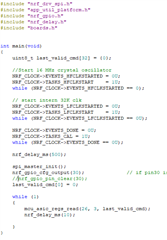
    int main(void)
    {
        uint8_t last_valid_cmd[32] = {0};
        
        //Start 16 MHz crystal oscillator
        NRF_CLOCK->EVENTS_HFCLKSTARTED = 0U;
        NRF_CLOCK->TASKS_HFCLKSTART    = 1U;
        while (NRF_CLOCK->EVENTS_HFCLKSTARTED == 0);           // Wait for the external oscillator to start up
    
        // start intern 32K clk
        NRF_CLOCK->EVENTS_LFCLKSTARTED = 0U;
        NRF_CLOCK->TASKS_LFCLKSTART    = 1U;
        while (NRF_CLOCK->EVENTS_LFCLKSTARTED == 0U);
    
        NRF_CLOCK->EVENTS_DONE = 0U;
        NRF_CLOCK->TASKS_CAL = 1U;
        while (NRF_CLOCK->EVENTS_DONE == 0U);
        
        nrf_delay_ms(500);                                     // wait for ASIC    
            
        spi_master_init();
        nrf_gpio_cfg_output(30);              // if pin30 is not set output and set1/clear0,spi sck is not right
        //nrf_gpio_pin_clear(30);
        last_valid_cmd[0] = 0;
        
        while (1)
        {
            mcu_asic_regs_read(26, 3, last_valid_cmd);
            nrf_delay_ms(10);
    
        }
    }
    
            /*NRF_CLOCK->TASKS_HFCLKSTOP = 1U;
            NRF_POWER->TASKS_LOWPWR = 1;
            __SEV();
            __WFE();
            __WFE();*/

  • Again, I don't think the problem is from the initializing of the GPIO as the previous project didn't have the gaps when i initialized the GPIO. I first observed the gaps when the last_valid_cmd[0] = 0 was included. 

Reply Children
No Data
Related