This post is older than 2 years and might not be relevant anymore
More Info: Consider searching for newer posts

UART TxD pin assignment inconsistency between PSEL.TXD and Serialization UART for PCA10056

Hi,

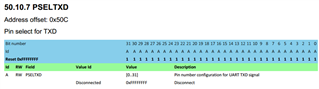
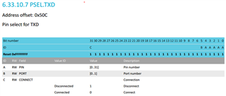
In the registery definition of nRF52840 it is stated for PSEL.TXD:

Reg ID: A -> from bit 0 til 4 for Pin selection

Reg ID: B -> bit 5 for Port number

In this case, we should conclude that the TxD pin of the UART can only be mapped to P1.0 to P1.4 and P0.0 to P0.4.

Am I right?

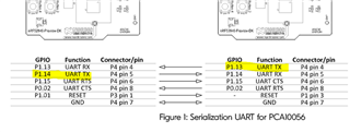
Conversely, in the serialization user guide:

(https://www.nordicsemi.com/DocLib/Content/SDK_Doc/nRF5_SDK/v15-2-0/nrf51_setups_serialization?21#serialization_hardware_uart)

we can see that the recommended connection between the boards PCA10056, implies that TxD is mapped to P1.13 or P1.14.

How this could be possible?

Any help is welcomed.

Parents Reply
  • Hi Peter,

    Thanks for your response but I need further clarification.

    This is quite surprising. In the PSEL.TxD of the nRF52832, the PSEL register use bit masking to indicate pin location.

    If we follow your response this mean that we have 2^32-1 location for TxD pin.

    I should have probably interpreted wrongly that bit masking was required.

    Should we consider that for nRF52832, pin selection is done using bit masking and with nRF52840, the selected pin number should be written in binary into the LSB portion of the register?

    Regards,

Children
Related