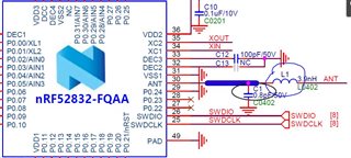
You could say they are one in the same. Primarily given the layout, stack up and placement of the dk this sch is for L1 and C1, optimizes the impedance to provide the best return loss over the bandwidth of interest. For RF, matching and filtering are tightly coupled. For this simple example however thinking of it as only matching makes more sense since the rejection and Q of the filter will out likely not give you that "filter" effect.
What you define as much is up to you. The main purpose of the components is still to filter the harmonics generated by the PA in the radio. With the components you should expect >30 dB attenuation compared with if they are not there.
The chip is reasonably well matched at fundamental, and output power should be quite good without the components, depending on your layout. You still need to measure the harmonic emissions and populate L1 and C1 accordingly, especially if you plan on using the higher output power settings. Even if you populate the reference design values (3.9nH and 0.8 pF) these might not be the optimal values for your layout and might require slight adjustment.