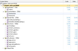
I am using the PWM app from nRF51_SDK_10.0.0_dc26b5e\components\libraries\pwm. I have loaded s110, and am running no other code.
The application hangs on the second cycle (duty factor = 1%) with LED0 permanently on, LED1 off.
The freeze occurs at:
while (app_pwm_channel_duty_set(&PWM1, 0, value) == NRF_ERROR_BUSY);
I understand from this forum that the problem might arise from an interrupt occurring before duty set completes
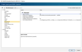
Disabling the softdevice (presumably a source of interrupts) with:
#define USE_WITH_SOFTDEVICE 0
does not resolve the problem
The debugger hangs on ISR_HANDLER ExternalISR9. However I expect that this is not a useful diagnostic since I understand that the debugger copes poorly with interrupts
I have read related posts but have run out of ideas - short of programming a 'scheduler', which seems a lot of work
What else could I do to ensure app_pwm_channel_duty_set(&PWM1, 0, value) completes?
Many thanks
/* Copyright (c) 2015 Nordic Semiconductor. All Rights Reserved.
 *
 * The information contained herein is property of Nordic Semiconductor ASA.
 * Terms and conditions of usage are described in detail in NORDIC
 * SEMICONDUCTOR STANDARD SOFTWARE LICENSE AGREEMENT.
 *
 * Licensees are granted free, non-transferable use of the information. NO
 * WARRANTY of ANY KIND is provided. This heading must NOT be removed from
 * the file.
 *
 */

#include "app_pwm.h"
#include "nrf_drv_timer.h"
#include "nrf_drv_ppi.h"
#include "nrf_drv_common.h"
#include "nrf_drv_gpiote.h"
#include "nrf_gpiote.h"
#include "nrf_gpio.h"
#include "app_util.h"
#include "app_util_platform.h"
#include "nrf_assert.h"

#define APP_PWM_CHANNEL_INITIALIZED                1
#define APP_PWM_CHANNEL_UNINITIALIZED              0

#define APP_PWM_CHANNEL_ENABLED                    1
#define APP_PWM_CHANNEL_DISABLED                   0

#define TIMER_PRESCALER_MAX                        9
#define TIMER_MAX_PULSEWIDTH_US_ON_16M             4095

#define APP_PWM_REQUIRED_PPI_CHANNELS_PER_INSTANCE 2
#define APP_PWM_REQUIRED_PPI_CHANNELS_PER_CHANNEL  2

#define UNALLOCATED                                0xFFFFFFFFUL
#define BUSY_STATE_CHANGING                        0xFE
#define BUSY_STATE_IDLE                            0xFF

#define PWM_MAIN_CC_CHANNEL                        2
#define PWM_SECONDARY_CC_CHANNEL                   3

/**
 * @brief PWM busy status
 *
 * Stores the number of a channel being currently updated.
 *
 */
static volatile uint8_t  m_pwm_busy[TIMER_COUNT];


/**
 * @brief New duty cycle value
 *
 * When the channel duty cycle reaches this value, the update process is complete.
 */
static volatile uint32_t m_pwm_target_value[TIMER_COUNT];


/**
 * @brief PWM ready counter
 *
 * The value in this counter is decremented in every PWM cycle after initiating the update.
 * If an event handler function was specified by the user, it is being called
 * after two cycle events (at least one full PWM cycle).
 */
volatile uint8_t m_pwm_ready_counter[TIMER_COUNT][APP_PWM_CHANNELS_PER_INSTANCE];

/**
 * @brief Pointers to instances
 *
 * This array connects any active timer instance number with the pointer to the PWM instance.
 * It is used by the interrupt runtime.
 */
static const app_pwm_t * m_instances[TIMER_COUNT];

// Macros for getting the polarity of given instance/channel.
#define POLARITY_ACTIVE(INST,CH)   (( ((INST)->p_cb)->channels_cb[(CH)].polarity == \
                 APP_PWM_POLARITY_ACTIVE_LOW)?(0):(1))
#define POLARITY_INACTIVE(INST,CH) (( ((INST)->p_cb)->channels_cb[(CH)].polarity == \
                 APP_PWM_POLARITY_ACTIVE_LOW)?(1):(0))

//lint -save -e534

/**
 * @brief Workaround for PAN-73.
 *
 * @param[in] timer     Timer.
 * @param[in] enable    Enable or disable.
 */
static void pan73_workaround(NRF_TIMER_Type * p_timer, bool enable)
{
#ifdef NRF51
    if (p_timer == NRF_TIMER0)
    {
        *(uint32_t *)0x40008C0C = (enable ? 1 : 0);
    }
    else if (p_timer == NRF_TIMER1)
    {
        *(uint32_t *)0x40009C0C = (enable ? 1 : 0);
    }
    else if (p_timer == NRF_TIMER2)
    {
        *(uint32_t *)0x4000AC0C = (enable ? 1 : 0);
    }
#endif
    return;
}


bool app_pwm_busy_check(app_pwm_t const * const p_instance)
{
    uint8_t busy_state = (m_pwm_busy[p_instance->p_timer->instance_id]);
    bool busy = true;
    if (busy_state != BUSY_STATE_IDLE)
    {
        if (busy_state != BUSY_STATE_CHANGING)
        {
            if (nrf_drv_timer_capture_get(p_instance->p_timer, (nrf_timer_cc_channel_t) busy_state)
                == m_pwm_target_value[p_instance->p_timer->instance_id])
            {
                m_pwm_busy[p_instance->p_timer->instance_id] = BUSY_STATE_IDLE;
                busy = false;
            }
        }
    }
    else
    {
        busy = false;
    }
    return busy;
}


/**
 * @brief Function for enabling the IRQ for a given PWM instance.
 *
 * @param[in] p_instance  PWM instance.
 */
__STATIC_INLINE void pwm_irq_enable(app_pwm_t const * const p_instance)
{
    nrf_drv_timer_compare_int_enable(p_instance->p_timer, PWM_MAIN_CC_CHANNEL);
}


/**
 * @brief Function for disabling the IRQ for a given PWM instance.
 *
 * @param[in] p_instance  PWM instance.
 */
__STATIC_INLINE void pwm_irq_disable(app_pwm_t const * const p_instance)
{
    nrf_drv_timer_compare_int_disable(p_instance->p_timer, PWM_MAIN_CC_CHANNEL);
}


/**
 * @brief Function for disabling PWM channel PPI.
 *
 * @param[in] p_instance  PWM instance.
 */
__STATIC_INLINE void pwm_channel_ppi_disable(app_pwm_t const * const p_instance, uint8_t channel)
{
    app_pwm_cb_t * p_cb = p_instance->p_cb;

    nrf_drv_ppi_channel_disable(p_cb->channels_cb[channel].ppi_channels[0]);
    nrf_drv_ppi_channel_disable(p_cb->channels_cb[channel].ppi_channels[1]);
}


/**
 * @brief Function for disabling PWM PPI.
 *
 * @param[in] p_instance  PWM instance.
 */
__STATIC_INLINE void pwm_ppi_disable(app_pwm_t const * const p_instance)
{
    app_pwm_cb_t * p_cb = p_instance->p_cb;

    nrf_drv_ppi_channel_disable(p_cb->ppi_channels[0]);
    nrf_drv_ppi_channel_disable(p_cb->ppi_channels[1]);
}


/**
 * @brief This function is called on interrupt after duty set.
 *
 * @param[in] timer                 Timer used by PWM.
 * @param[in] timer_instance_id     Timer index.
 */
void pwm_ready_tick(nrf_timer_event_t event_type, void * p_context)
{
    uint32_t timer_instance_id = (uint32_t)p_context;
    uint8_t disable = 1;

    for (uint8_t channel = 0; channel < APP_PWM_CHANNELS_PER_INSTANCE; ++channel)
    {
        if (m_pwm_ready_counter[timer_instance_id][channel])
        {
            --m_pwm_ready_counter[timer_instance_id][channel];
            if (!m_pwm_ready_counter[timer_instance_id][channel])
            {
                app_pwm_cb_t * p_cb = m_instances[timer_instance_id]->p_cb;
                p_cb->p_ready_callback(timer_instance_id);
            }
            else
            {
                disable = 0;
            }
        }
    }

    if (disable)
    {
        pwm_irq_disable(m_instances[timer_instance_id]);
    }
}


/**
 * @brief Function for resource de-allocation.
 *
 * @param[in] p_instance       PWM instance.
 */
//lint -e{650}
static void pwm_dealloc(app_pwm_t const * const p_instance)
{
    app_pwm_cb_t * p_cb = p_instance->p_cb;

    for (uint8_t i = 0; i < APP_PWM_REQUIRED_PPI_CHANNELS_PER_INSTANCE; ++i)
    {
        if (p_cb->ppi_channels[i] != (nrf_ppi_channel_t)(uint8_t)(UNALLOCATED))
        {
            nrf_drv_ppi_channel_free(p_cb->ppi_channels[i]);
        }
    }
    if (p_cb->ppi_group != (nrf_ppi_channel_group_t)UNALLOCATED)
    {
        nrf_drv_ppi_group_free(p_cb->ppi_group);
    }

    for (uint8_t ch = 0; ch < APP_PWM_CHANNELS_PER_INSTANCE; ++ch)
    {
        for (uint8_t i = 0; i < APP_PWM_REQUIRED_PPI_CHANNELS_PER_CHANNEL; ++i)
        {
            if (p_cb->channels_cb[ch].ppi_channels[i] != (nrf_ppi_channel_t)UNALLOCATED)
            {
                nrf_drv_ppi_channel_free(p_cb->channels_cb[ch].ppi_channels[i]);
                p_cb->channels_cb[ch].ppi_channels[i] = (nrf_ppi_channel_t)UNALLOCATED;
            }
        }
        if (p_cb->channels_cb[ch].gpio_pin != UNALLOCATED)
        {
            nrf_drv_gpiote_out_uninit(p_cb->channels_cb[ch].gpio_pin);
            p_cb->channels_cb[ch].gpio_pin = UNALLOCATED;
        }
        p_cb->channels_cb[ch].initialized = APP_PWM_CHANNEL_UNINITIALIZED;
    }
    nrf_drv_timer_uninit(p_instance->p_timer);
    return;
}


/**
 * @brief PWM state transition from (0%, 100%) to 0% or 100%.
 *
 * @param[in] p_instance       PWM instance.
 * @param[in] channel          PWM channel number.
 * @param[in] ticks            Number of clock ticks.
 */
static void pwm_transition_n_to_0or100(app_pwm_t const * const p_instance,
                                       uint8_t channel, uint16_t ticks)
{
    app_pwm_cb_t            * p_cb     = p_instance->p_cb;
    app_pwm_channel_cb_t    * p_ch_cb  = &p_cb->channels_cb[channel];
    nrf_ppi_channel_group_t   p_ppigrp = p_cb->ppi_group;

    pwm_ppi_disable(p_instance);
    nrf_drv_ppi_group_clear(p_ppigrp);
    nrf_drv_ppi_channels_include_in_group(
            nrf_drv_ppi_channel_to_mask(p_ch_cb->ppi_channels[0]) |
            nrf_drv_ppi_channel_to_mask(p_ch_cb->ppi_channels[1]),
            p_ppigrp);

    if (!ticks)
    {
        nrf_drv_ppi_channel_assign(p_cb->ppi_channels[0],
                    nrf_drv_timer_compare_event_address_get(p_instance->p_timer, channel),
                    nrf_drv_ppi_task_addr_group_disable_get(p_ppigrp));
        nrf_drv_timer_compare(p_instance->p_timer, (nrf_timer_cc_channel_t) PWM_SECONDARY_CC_CHANNEL, 0, false);
        m_pwm_target_value[p_instance->p_timer->instance_id] =
            nrf_drv_timer_capture_get(p_instance->p_timer, (nrf_timer_cc_channel_t) channel);
        nrf_drv_ppi_channel_assign(p_cb->ppi_channels[1],
                    nrf_drv_timer_compare_event_address_get(p_instance->p_timer, channel),
                    nrf_drv_timer_capture_task_address_get(p_instance->p_timer, PWM_SECONDARY_CC_CHANNEL));
    }
    else
    {
        ticks = p_cb->period;
        nrf_drv_ppi_channel_assign(p_cb->ppi_channels[0],
                    nrf_drv_timer_compare_event_address_get(p_instance->p_timer, PWM_MAIN_CC_CHANNEL),
                    nrf_drv_ppi_task_addr_group_disable_get(p_ppigrp));
        // Set secondary CC channel to non-zero value:
        nrf_drv_timer_compare(p_instance->p_timer, (nrf_timer_cc_channel_t) PWM_SECONDARY_CC_CHANNEL, 1, false);
        m_pwm_target_value[p_instance->p_timer->instance_id] = 0;
        // The captured value will be equal to 0, because timer clear on main PWM CC channel compare is enabled.
        nrf_drv_ppi_channel_assign(p_cb->ppi_channels[1],
                    nrf_drv_timer_compare_event_address_get(p_instance->p_timer, PWM_MAIN_CC_CHANNEL),
                    nrf_drv_timer_capture_task_address_get(p_instance->p_timer, PWM_SECONDARY_CC_CHANNEL));
    }

    nrf_drv_ppi_channel_enable(p_cb->ppi_channels[0]);
    nrf_drv_ppi_channel_enable(p_cb->ppi_channels[1]);

    p_ch_cb->pulsewidth = ticks;
    m_pwm_busy[p_instance->p_timer->instance_id] = PWM_SECONDARY_CC_CHANNEL;
}


/**
 * @brief PWM state transition from (0%, 100%) to (0%, 100%).
 *
 * @param[in] p_instance       PWM instance.
 * @param[in] channel          PWM channel number.
 * @param[in] ticks            Number of clock ticks.
 */
static void pwm_transition_n_to_m(app_pwm_t const * const p_instance,
                                  uint8_t channel, uint16_t ticks)
{
    app_pwm_cb_t            * p_cb     = p_instance->p_cb;
    app_pwm_channel_cb_t    * p_ch_cb  = &p_cb->channels_cb[channel];
    nrf_ppi_channel_group_t   p_ppigrp = p_cb->ppi_group;

    pwm_ppi_disable(p_instance);
    nrf_drv_ppi_group_clear(p_ppigrp);
    nrf_drv_ppi_channels_include_in_group(
        nrf_drv_ppi_channel_to_mask(p_cb->ppi_channels[0]) |
        nrf_drv_ppi_channel_to_mask(p_cb->ppi_channels[1]),
        p_ppigrp);

    nrf_drv_ppi_channel_assign(p_cb->ppi_channels[0],
                nrf_drv_timer_compare_event_address_get(p_instance->p_timer, PWM_SECONDARY_CC_CHANNEL),
                nrf_drv_timer_capture_task_address_get(p_instance->p_timer, channel));

    if (ticks + ((nrf_timer_frequency_get(p_instance->p_timer->p_reg) == NRF_TIMER_FREQ_16MHz) ? 1 : 0)
        < p_ch_cb->pulsewidth)
    {
        // For lower value, we need one more transition. Timer task delay is included.
        // If prescaler is enabled, one tick must be added because of 1 PCLK16M clock cycle delay.
        nrf_drv_ppi_channel_assign(p_cb->ppi_channels[1],
                nrf_drv_timer_compare_event_address_get(p_instance->p_timer, PWM_SECONDARY_CC_CHANNEL),
                nrf_drv_gpiote_out_task_addr_get(p_ch_cb->gpio_pin));
    }
    else
    {
        nrf_drv_ppi_channel_remove_from_group(p_cb->ppi_channels[1], p_ppigrp);
    }
    p_ch_cb->pulsewidth = ticks;
    nrf_drv_timer_compare(p_instance->p_timer, (nrf_timer_cc_channel_t) PWM_SECONDARY_CC_CHANNEL, ticks, false);
    nrf_drv_ppi_group_enable(p_ppigrp);

    m_pwm_target_value[p_instance->p_timer->instance_id] = ticks;
    m_pwm_busy[p_instance->p_timer->instance_id] = channel;
}


/**
 * @brief PWM state transition from 0% or 100% to (0%, 100%).
 *
 * @param[in] p_instance       PWM instance.
 * @param[in] channel          PWM channel number.
 * @param[in] ticks            Number of clock ticks.
 */
static void pwm_transition_0or100_to_n(app_pwm_t const * const p_instance,
                                       uint8_t channel, uint16_t ticks)
{
    app_pwm_cb_t            * p_cb      = p_instance->p_cb;
    app_pwm_channel_cb_t    * p_ch_cb   = &p_cb->channels_cb[channel];
    nrf_ppi_channel_group_t   p_ppigrp  = p_cb->ppi_group;
    nrf_timer_cc_channel_t    pwm_ch_cc = (nrf_timer_cc_channel_t)(channel);

    pwm_ppi_disable(p_instance);
    pwm_channel_ppi_disable(p_instance, channel);

    nrf_drv_timer_compare(p_instance->p_timer, pwm_ch_cc, ticks, false);
    nrf_drv_ppi_group_clear(p_ppigrp);
    nrf_drv_ppi_channels_include_in_group(
        nrf_drv_ppi_channel_to_mask(p_ch_cb->ppi_channels[0])|
        nrf_drv_ppi_channel_to_mask(p_ch_cb->ppi_channels[1]),
        p_ppigrp);

    if (!p_ch_cb->pulsewidth)
    {
        // Channel is at 0%.
        nrf_drv_ppi_channel_assign(p_cb->ppi_channels[0],
                    nrf_drv_timer_compare_event_address_get(p_instance->p_timer, channel),
                    nrf_drv_ppi_task_addr_group_enable_get(p_ppigrp));
        nrf_drv_timer_compare(p_instance->p_timer, (nrf_timer_cc_channel_t) PWM_SECONDARY_CC_CHANNEL, 0, false);
        m_pwm_target_value[p_instance->p_timer->instance_id] =
            nrf_drv_timer_capture_get(p_instance->p_timer, (nrf_timer_cc_channel_t) channel);
        nrf_drv_ppi_channel_assign(p_cb->ppi_channels[1],
                    nrf_drv_timer_compare_event_address_get(p_instance->p_timer, channel),
                    nrf_drv_timer_capture_task_address_get(p_instance->p_timer, PWM_SECONDARY_CC_CHANNEL));

    }
    else
    {
        // Channel is at 100%.
        nrf_drv_ppi_channel_assign(p_cb->ppi_channels[0],
                    nrf_drv_timer_compare_event_address_get(p_instance->p_timer, PWM_MAIN_CC_CHANNEL),
                    nrf_drv_ppi_task_addr_group_enable_get(p_ppigrp));
        // Set secondary CC channel to non-zero value:
        nrf_drv_timer_compare(p_instance->p_timer, (nrf_timer_cc_channel_t) PWM_SECONDARY_CC_CHANNEL, 1, false);
        m_pwm_target_value[p_instance->p_timer->instance_id] = 0;
        // The captured value will be equal to 0, because timer clear on main PWM CC channel compare is enabled.
        nrf_drv_ppi_channel_assign(p_cb->ppi_channels[1],
                    nrf_drv_timer_compare_event_address_get(p_instance->p_timer, PWM_MAIN_CC_CHANNEL),
                    nrf_drv_timer_capture_task_address_get(p_instance->p_timer, PWM_SECONDARY_CC_CHANNEL));
    }
    nrf_drv_ppi_channel_enable(p_cb->ppi_channels[0]);
    nrf_drv_ppi_channel_enable(p_cb->ppi_channels[1]);

    p_ch_cb->pulsewidth = ticks;
    m_pwm_busy[p_instance->p_timer->instance_id] = PWM_SECONDARY_CC_CHANNEL;
}


/**
 * @brief PWM state transition from 0% or 100% to 0% or 100%.
 *
 * @param[in] p_instance       PWM instance.
 * @param[in] channel          PWM channel number.
 * @param[in] ticks            Number of clock ticks.
 */
static void pwm_transition_0or100_to_0or100(app_pwm_t const * const p_instance,
                                            uint8_t channel, uint16_t ticks)
{
    app_pwm_cb_t         * p_cb      = p_instance->p_cb;
    app_pwm_channel_cb_t * p_ch_cb   = &p_cb->channels_cb[channel];
    nrf_timer_cc_channel_t pwm_ch_cc = (nrf_timer_cc_channel_t)(channel);

    pwm_ppi_disable(p_instance);
    pwm_channel_ppi_disable(p_instance, channel);
    if (!ticks)
    {
        // Set to 0%.
        nrf_drv_gpiote_out_task_force(p_ch_cb->gpio_pin, POLARITY_INACTIVE(p_instance, channel));
    }
    else if (ticks >= p_cb->period)
    {
        // Set to 100%.
        ticks = p_cb->period;
        nrf_drv_gpiote_out_task_force(p_ch_cb->gpio_pin, POLARITY_ACTIVE(p_instance, channel));
    }
    nrf_drv_timer_compare(p_instance->p_timer, pwm_ch_cc, ticks, false);
    p_ch_cb->pulsewidth = ticks;

    m_pwm_busy[p_instance->p_timer->instance_id] = BUSY_STATE_IDLE;
    return;
}


ret_code_t app_pwm_channel_duty_ticks_set(app_pwm_t const * const p_instance,
                                          uint8_t           channel,
                                          uint16_t          ticks)
{
    app_pwm_cb_t         * p_cb    = p_instance->p_cb;
    app_pwm_channel_cb_t * p_ch_cb = &p_cb->channels_cb[channel];

    ASSERT(channel < APP_PWM_CHANNELS_PER_INSTANCE);
    ASSERT(p_ch_cb->initialized == APP_PWM_CHANNEL_INITIALIZED);

    if (p_cb->state != NRF_DRV_STATE_POWERED_ON)
    {
        return NRF_ERROR_INVALID_STATE;
    }
    if (ticks == p_ch_cb->pulsewidth)
    {
        if (p_cb->p_ready_callback)
        {
            p_cb->p_ready_callback(p_instance->p_timer->instance_id);
        }
        return NRF_SUCCESS;     // No action required.
    }
    if (app_pwm_busy_check(p_instance))
    {
        return NRF_ERROR_BUSY;  // PPI channels for synchronization are still in use.
    }

    m_pwm_busy[p_instance->p_timer->instance_id] = BUSY_STATE_CHANGING;

    // Pulse width change sequence:
    if (!p_ch_cb->pulsewidth || p_ch_cb->pulsewidth >= p_cb->period)
    {
        // Channel is disabled (0%) or at 100%.
        if (!ticks || ticks >= p_cb->period)
        {
            // Set to 0 or 100%.
            pwm_transition_0or100_to_0or100(p_instance, channel, ticks);
        }
        else
        {
            // Other value.
            pwm_transition_0or100_to_n(p_instance, channel, ticks);
        }
    }
    else
    {
        // Channel is at other value.
        if (!ticks || ticks >= p_cb->period)
        {
            // Disable channel (set to 0%) or set to 100%.
            pwm_transition_n_to_0or100(p_instance, channel, ticks);
        }
        else
        {
            // Set to any other value.
            pwm_transition_n_to_m(p_instance, channel, ticks);
        }
    }
    if (p_instance->p_cb->p_ready_callback)
    {
        //PWM ready interrupt handler will be called after one full period.
        m_pwm_ready_counter[p_instance->p_timer->instance_id][channel] = 2;
        pwm_irq_enable(p_instance);
    }
    return NRF_SUCCESS;
}

uint16_t app_pwm_channel_duty_ticks_get(app_pwm_t const * const p_instance, uint8_t channel)
{
    app_pwm_cb_t         * p_cb      = p_instance->p_cb;
    app_pwm_channel_cb_t * p_ch_cb   = &p_cb->channels_cb[channel];

    return p_ch_cb->pulsewidth;
}

uint16_t app_pwm_cycle_ticks_get(app_pwm_t const * const p_instance)
{
    app_pwm_cb_t * p_cb = p_instance->p_cb;

    return (uint16_t)p_cb->period;
}

ret_code_t app_pwm_channel_duty_set(app_pwm_t const * const p_instance,
                                  uint8_t channel, app_pwm_duty_t duty)
{
    uint32_t ticks = ((uint32_t)app_pwm_cycle_ticks_get(p_instance) * (uint32_t)duty) / 100UL;
    return app_pwm_channel_duty_ticks_set(p_instance, channel, ticks);
}


app_pwm_duty_t app_pwm_channel_duty_get(app_pwm_t const * const p_instance, uint8_t channel)
{
    uint32_t value = ((uint32_t)app_pwm_channel_duty_ticks_get(p_instance, channel) * 100UL) \
                     / (uint32_t)app_pwm_cycle_ticks_get(p_instance);

    return (app_pwm_duty_t)value;
}


/**
 * @brief Function for initializing the PWM channel.
 *
 * @param[in] p_instance       PWM instance.
 * @param[in] channel          Channel number.
 * @param[in] pin              GPIO pin number.
 *
 * @retval    NRF_SUCCESS If initialization was successful.
 * @retval    NRF_ERROR_NO_MEM If there were not enough free resources.
 * @retval    NRF_ERROR_INVALID_STATE If the timer is already in use or initialization failed.
 */
static ret_code_t app_pwm_channel_init(app_pwm_t const * const p_instance, uint8_t channel,
                                     uint32_t pin, app_pwm_polarity_t polarity)
{
    ASSERT(channel < APP_PWM_CHANNELS_PER_INSTANCE);
    app_pwm_cb_t * p_cb = p_instance->p_cb;
    app_pwm_channel_cb_t * p_channel_cb = &p_cb->channels_cb[channel];

    if (p_cb->state != NRF_DRV_STATE_UNINITIALIZED)
    {
        return NRF_ERROR_INVALID_STATE;
    }

    p_channel_cb->pulsewidth = 0;
    p_channel_cb->polarity   = polarity;
    ret_code_t err_code;

    /* GPIOTE setup: */
    nrf_drv_gpiote_out_config_t out_cfg = GPIOTE_CONFIG_OUT_TASK_TOGGLE( POLARITY_INACTIVE(p_instance, channel) );
    err_code = nrf_drv_gpiote_out_init((nrf_drv_gpiote_pin_t)pin,&out_cfg);
    if (err_code != NRF_SUCCESS)
    {
        return NRF_ERROR_NO_MEM;
    }
    p_cb->channels_cb[channel].gpio_pin = pin;

    // Set output to inactive state.
    if (polarity)
    {
        nrf_gpio_pin_clear(pin);
    }
    else
    {
        nrf_gpio_pin_set(pin);
    }

    /* PPI setup: */
    for (uint8_t i = 0; i < APP_PWM_REQUIRED_PPI_CHANNELS_PER_CHANNEL; ++i)
    {
        if (nrf_drv_ppi_channel_alloc(&p_channel_cb->ppi_channels[i]) != NRF_SUCCESS)
        {
            return NRF_ERROR_NO_MEM; // Resource de-allocation is done by callee.
        }
    }

    nrf_drv_ppi_channel_disable(p_channel_cb->ppi_channels[0]);
    nrf_drv_ppi_channel_disable(p_channel_cb->ppi_channels[1]);
    nrf_drv_ppi_channel_assign(p_channel_cb->ppi_channels[0],
                               nrf_drv_timer_compare_event_address_get(p_instance->p_timer, channel),
                               nrf_drv_gpiote_out_task_addr_get(p_channel_cb->gpio_pin));
    nrf_drv_ppi_channel_assign(p_channel_cb->ppi_channels[1],
                               nrf_drv_timer_compare_event_address_get(p_instance->p_timer, PWM_MAIN_CC_CHANNEL),
                               nrf_drv_gpiote_out_task_addr_get(p_channel_cb->gpio_pin));

    p_channel_cb->initialized = APP_PWM_CHANNEL_INITIALIZED;
    m_pwm_ready_counter[p_instance->p_timer->instance_id][channel] = 0;

    return NRF_SUCCESS;
}


/**
 * @brief Function for calculating target timer frequency, which will allow to set given period length.
 *
 * @param[in] period_us       Desired period in microseconds.
 *
 * @retval    Timer frequency.
 */
//inline nrf_timer_frequency_t pwm_calculate_timer_frequency(uint32_t period_us)
//rjw change.  See
//https://devzone.nordicsemi.com/f/nordic-q-a/10175/gcc-using-app_pwm-with--o0--g3-debug-mode-cause-unknown-function/37727#37727
nrf_timer_frequency_t pwm_calculate_timer_frequency(uint32_t period_us)
{
    uint32_t f   = (uint32_t)NRF_TIMER_FREQ_16MHz;
    uint32_t min = (uint32_t)NRF_TIMER_FREQ_31250Hz;

    while ((period_us > TIMER_MAX_PULSEWIDTH_US_ON_16M) && (f < min))
    {
        period_us >>= 1;
        ++f;
    }
    return (nrf_timer_frequency_t)f;
}


ret_code_t app_pwm_init(app_pwm_t const * const p_instance, app_pwm_config_t const * const p_config,
                        app_pwm_callback_t p_ready_callback)
{
    ASSERT(p_instance);

    if (!p_config)
    {
        return NRF_ERROR_INVALID_DATA;
    }

    app_pwm_cb_t * p_cb = p_instance->p_cb;

    if (p_cb->state != NRF_DRV_STATE_UNINITIALIZED)
    {
        return NRF_ERROR_INVALID_STATE;
    }

    uint32_t err_code = nrf_drv_ppi_init();
    if ((err_code != NRF_SUCCESS) && (err_code != MODULE_ALREADY_INITIALIZED))
    {
        return NRF_ERROR_NO_MEM;
    }


    if (!nrf_drv_gpiote_is_init())
    {
        err_code = nrf_drv_gpiote_init();
        if (err_code != NRF_SUCCESS)
		{
			return NRF_ERROR_INTERNAL;
		}
    }

    // Innitialize resource status:
    p_cb->ppi_channels[0] = (nrf_ppi_channel_t)UNALLOCATED;
    p_cb->ppi_channels[1] = (nrf_ppi_channel_t)UNALLOCATED;
    p_cb->ppi_group       = (nrf_ppi_channel_group_t)UNALLOCATED;

    for (uint8_t i = 0; i < APP_PWM_CHANNELS_PER_INSTANCE; ++i)
    {
        p_cb->channels_cb[i].initialized     = APP_PWM_CHANNEL_UNINITIALIZED;
        p_cb->channels_cb[i].ppi_channels[0] = (nrf_ppi_channel_t)UNALLOCATED;
        p_cb->channels_cb[i].ppi_channels[1] = (nrf_ppi_channel_t)UNALLOCATED;
        p_cb->channels_cb[i].gpio_pin        = UNALLOCATED;
    }

    // Allocate PPI channels and groups:
    for (uint8_t i = 0; i < APP_PWM_REQUIRED_PPI_CHANNELS_PER_INSTANCE; ++i)
    {
        if (nrf_drv_ppi_channel_alloc(&p_cb->ppi_channels[i]) != NRF_SUCCESS)
        {
            pwm_dealloc(p_instance);
            return NRF_ERROR_NO_MEM;
        }
    }
    if (nrf_drv_ppi_group_alloc(&p_cb->ppi_group) != NRF_SUCCESS)
    {
        pwm_dealloc(p_instance);
        return NRF_ERROR_NO_MEM;
    }

    // Initialize channels:
    for (uint8_t i = 0; i < APP_PWM_CHANNELS_PER_INSTANCE; ++i)
    {
        if (p_config->pins[i] != APP_PWM_NOPIN)
        {
            err_code = app_pwm_channel_init(p_instance, i, p_config->pins[i], p_config->pin_polarity[i]);
            if (err_code != NRF_SUCCESS)
            {
                pwm_dealloc(p_instance);
                return err_code;
            }
            app_pwm_channel_duty_ticks_set(p_instance, i, 0);
        }
    }

    // Initialize timer:
    nrf_timer_frequency_t  timer_freq = pwm_calculate_timer_frequency(p_config->period_us);
    nrf_drv_timer_config_t timer_cfg  = {
        .frequency          = timer_freq,
        .mode               = NRF_TIMER_MODE_TIMER,
        .bit_width          = NRF_TIMER_BIT_WIDTH_16,
        .interrupt_priority = APP_IRQ_PRIORITY_HIGH, //rjw changed but with no improvement
        .p_context          = (void *) (uint32_t) p_instance->p_timer->instance_id
    };
    err_code = nrf_drv_timer_init(p_instance->p_timer, &timer_cfg,
                                  pwm_ready_tick);
    if (err_code != NRF_SUCCESS)
    {
        pwm_dealloc(p_instance);
        return err_code;
    }

    uint32_t ticks = nrf_drv_timer_us_to_ticks(p_instance->p_timer, p_config->period_us);
    p_cb->period = ticks;
    nrf_drv_timer_clear(p_instance->p_timer);
    nrf_drv_timer_extended_compare(p_instance->p_timer, (nrf_timer_cc_channel_t) PWM_MAIN_CC_CHANNEL,
                                    ticks, NRF_TIMER_SHORT_COMPARE2_CLEAR_MASK, true);
    nrf_drv_timer_compare_int_disable(p_instance->p_timer, PWM_MAIN_CC_CHANNEL);

    p_cb->p_ready_callback = p_ready_callback;
    m_instances[p_instance->p_timer->instance_id] = p_instance;
    m_pwm_busy[p_instance->p_timer->instance_id] = BUSY_STATE_IDLE;
    p_cb->state = NRF_DRV_STATE_INITIALIZED;

    return NRF_SUCCESS;
}


void app_pwm_enable(app_pwm_t const * const p_instance)
{
    app_pwm_cb_t * p_cb = p_instance->p_cb;

    ASSERT(p_cb->state != NRF_DRV_STATE_UNINITIALIZED);

    for (uint32_t channel = 0; channel < APP_PWM_CHANNELS_PER_INSTANCE; ++channel)
    {
        app_pwm_channel_cb_t * p_ch_cb = &p_cb->channels_cb[channel];
        m_pwm_ready_counter[p_instance->p_timer->instance_id][channel] = 0;
        if (p_ch_cb->initialized)
        {
            nrf_drv_gpiote_out_task_force(p_ch_cb->gpio_pin, POLARITY_INACTIVE(p_instance, channel));
            nrf_drv_gpiote_out_task_enable(p_ch_cb->gpio_pin);
            p_ch_cb->pulsewidth = 0;
        }
    }
    m_pwm_busy[p_instance->p_timer->instance_id] = BUSY_STATE_IDLE;
    pan73_workaround(p_instance->p_timer->p_reg, true);
    nrf_drv_timer_clear(p_instance->p_timer);
    nrf_drv_timer_enable(p_instance->p_timer);

    p_cb->state = NRF_DRV_STATE_POWERED_ON;
    return;
}


void app_pwm_disable(app_pwm_t const * const p_instance)
{
    app_pwm_cb_t * p_cb = p_instance->p_cb;

    ASSERT(p_cb->state != NRF_DRV_STATE_UNINITIALIZED);

    nrf_drv_timer_disable(p_instance->p_timer);
    pwm_irq_disable(p_instance);
    for (uint8_t ppi_channel = 0; ppi_channel < APP_PWM_REQUIRED_PPI_CHANNELS_PER_INSTANCE; ++ppi_channel)
    {
        nrf_drv_ppi_channel_disable(p_cb->ppi_channels[ppi_channel]);
    }
    for (uint8_t channel = 0; channel < APP_PWM_CHANNELS_PER_INSTANCE; ++channel)
    {
        app_pwm_channel_cb_t * p_ch_cb = &p_cb->channels_cb[channel];
        if (p_ch_cb->initialized)
        {
            uint8_t polarity = POLARITY_INACTIVE(p_instance, channel);
            if (polarity)
            {
                nrf_gpio_pin_set(p_ch_cb->gpio_pin);
            }
            else
            {
                nrf_gpio_pin_clear(p_ch_cb->gpio_pin);
            }
            nrf_drv_gpiote_out_task_disable(p_ch_cb->gpio_pin);
            nrf_drv_ppi_channel_disable(p_ch_cb->ppi_channels[0]);
            nrf_drv_ppi_channel_disable(p_ch_cb->ppi_channels[1]);
        }
    }
    pan73_workaround(p_instance->p_timer->p_reg, false);

    p_cb->state = NRF_DRV_STATE_INITIALIZED;
    return;
}


ret_code_t app_pwm_uninit(app_pwm_t const * const p_instance)
{
    app_pwm_cb_t * p_cb = p_instance->p_cb;

    if (p_cb->state == NRF_DRV_STATE_POWERED_ON)
    {
        app_pwm_disable(p_instance);
    }
    else if (p_cb->state == NRF_DRV_STATE_UNINITIALIZED)
    {
        return NRF_ERROR_INVALID_STATE;
    }
    pwm_dealloc(p_instance);

    p_cb->state = NRF_DRV_STATE_UNINITIALIZED;
    return NRF_SUCCESS;
}


//lint -restore