This post is older than 2 years and might not be relevant anymore
More Info: Consider searching for newer posts

Theoretical RSSI and current measurement

I want to compare some values of RSSI that I have obtained in a test that I have made with its corresponding theoretical value and to calculate this theoretical value I will use the following formula obtained here.

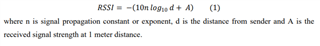
and I would like to know that parameter A , that is to say, the theoretical RSSI at a distance of one meter for a transmission power of 8, 0 and - 8 decibels for nRF52840 preview DK

On the other hand, I wanted to calculate the consumption of nrf52840 PDK when using the NUS example for peripheral and I got a graph similar to a periodic triangular signal, you know what the problem is?

  • Hi,


    The free-space path loss over 1m is approximately 40 dB. This means A = Pout + Gtx + Grx - Lpath


    I would need some more information, e.g. a measurement plot, to know if the current consumption is correct or not, and what the issue might be. That said though, under normal operation the current consumption will vary depending on the task the SoC performs at a given moment. If you are running an unmodified example from the SDK on a Nordic DK it should be working as intended.


    Best regards,

    Andreas

  • Hi Andreas, thank you for your answer.

    This Value 40 dB, this value of 40 decibels to which transmission power corresponds? For TX = 8 dB? and for a transmission power of 0 dB and -8 dB?. I would also like to know if it is normal for RSSI values to fluctuate a lot?

    On the other hand, I can't show you the graphics that I got because I don't have any images but I can tell you the material used and the procedure that I followed.

         Material:

              - National Instruments VB-8034  (oscilloscope)

              - Tectronix TCPA300 (amplifier and AC / DC converter)

              - Tectronix TCP305A (current probe)

    Procedure:

        1. I connect the probe to the AD-DC converter and output of this converter to the input of the oscilloscope

        2. I download the example of ble_app_uart_c to a development board nrf52840 PDK and ble_app_uart to another           nrf52840 pdk. 

        3. As I mentioned in this post, to be able to use the Li-Po battery, first I have to connect the board through USB to the computer, then connect the Li-Po battery to the board and finally remove the usb cable.

        4. Connected the probe to the battery power cable.

    With this procedure I got a triangular signal, Can this happen when working with the preview of nrf52840 dk?

  • Hi,


    40 dB is the path loss, the amount the signal is weakened from propagating 1m free-space. It is the same for all TX levels, and will make received power proportional with the transmitted power, as antenna gain and path loss can be considered constant.

    The RSSI will probably fluctuate a bit as there will be multipath, fading and the likes. Even a minuscule change to the channel can change reflections etc. enough that you see a fluctuation in RSSI.


    As for the Li-Po supply I have never heard that this should be required. Have you made sure the power supply source is actually set up to Li-Po? See the development kit user guide.


    Best regards,

    Andreas

  • Hi,

    Thanks for your answer but now I do not know how to calculate the theoretical RSSI. What formula should I use for the theoretical calculation of RSSi for our boards? 

     Have you made sure the power supply source is actually set up to Li-Po?  Yes and I also tried whit the coin cell but it did not work either.

  • Hi,


    See my first reply: A = Pout + Gtx + Grx - Lpath

    • A = Theoretical RSSI at 1m
    • Pout = output power, in your case 8 dBm, 0 dBm or -8 dBm
    • Gtx = Gain of the transmitter antenna. I do not know what this is, if you do not you have to measure it. -5 to 0 dBi should be a fair ballpark estimate.
    • Grx = gain of the receiver antenna.  I do not know what this is, if you do not you have to measure it. -5 to 0 dBi should be a fair ballpark estimate.
    • Lpath = -40dB. Path loss over 1 meter

    E.g. Pout = 0 dBm, Gtx = Grx = 0 dBi:


    A = 0 dBm + 0 dBi + 0 dBi - 40dB = -40 dBm


    Instead, and probably more accurate in a non-ideal design, would be to just measure A. Setup a transmitter at 8dBm, 0dBm and -8dBm at 1m from the receiver, and read the RSSI.

    I am not familiar with the method to which you link, but as I understand it you need to determine n by calibrating the system. Set it up in a number of positions, distances etc., measure RSSI in that position and calculate the n for the position (you know A, and can measure d). If you are lucky there should not be a too large spread.


    Best regards,

    Andreas

Related