Hi, I try to adopt the twi_scanner example from the peripheral examples to the nRF52840 Dongle.
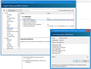
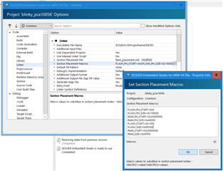
I followed the process in the following link with no success though.
What can I do to make it work?
Thank you
Hi, I try to adopt the twi_scanner example from the peripheral examples to the nRF52840 Dongle.
I followed the process in the following link with no success though.
What can I do to make it work?
Thank you