This post is older than 2 years and might not be relevant anymore
More Info: Consider searching for newer posts

nRF52840 Dongle Reset Issue

Hello,

I am having an issue where the nRF52840 dongle does not properly reset. I'd appreciate it anyone can help.

I was evaluating the DFU options, and erased the IC in the process. I am now trying to get it back to the default state. I used the J-Link debugger to flash the factory MBR, Bootloader (and changed the UICR to get 3.3v VDD out). I have two nRF52840 Dongles, one of the two does works fine (after going through the refresh process), and the other seems not. The one that is not working, actually does "work" when the J-Link debugger is attached.

When I attach the J-Link debugger, it does reset properly:

  • I am able to reset via the nrfjprog.
  • I am able to reset via the reset button.
  • The dongle gets listed in nRF Connect Desktop App.
  • Slow blinking red led is on.

When I do not attach the debugger:

  • reset button does not seem to put the device in reset
  • The dongle does not get listed in nRF Connect Desktop App.
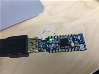
  • fast blinking red led is on.

Thanks,

Mak

Parents
  • Also are the two date codes on the nRF52840 dies identical? Reducing the load on VDD can help with this .. there is a load cap on RESET  so if the RESET pin is disabled that may help .. or 100k resistor J2 pin 5 to pin 1 to bleed some current into Vdd..

    POWER: Device does not start up in high voltage mode This anomaly applies to IC Rev. Rev 1, build codes QIAA-Cx0, CKAA-Cx0.

  • Yes, that looks correct. maybe try with something like 2k or 10k .. this is my reasoning from the Errata document:

    Workaround Do not draw current from VDD pin (external circuitry supply) during power up and ensure VDDH rise time to 3 V is below 1 ms.

    Oh, and hopefully you are not using a coin cell or other high impedance power source? That would give a slow rise time .. USB stuff should be fine

  • Hi, 

    I've tried 2k and the computer (Mac) gave a warning dialog that it was drawing too much power. I've also tried 10k, and got a same overdraw response. No luck so far.

    I am not using a coin cell - either from the computer or from a iPhone charger USB converter.

    I noticed something interesting. The non-working Dongle's GND constantly fluctuates between 1~4v (relative to USB GND) when the debug probe is not connected (when it is not working). When I attach the debug probe (starts working), it shows 45mV (relative to USB GND). I'm measuring the GND reading from the edge connector's GND pins. The USB GND pin is stable, but the edge GND pins fluctuates (if debugger not connected)...why would that happen??

    The working Dongle always have a GND around 1~20mV (relative to USB GND).

    Any suggestions appreciated.

    Thanks,

    Mak 

  • Excellent! This raises two issues, 1) FB2 has gone open-circuit, or got knocked off by the USB port plastic, so just short it out and 2) how can the supply current be so high when there is no Gnd connection, which implies the warning is not about supply but about current through the signal + or -.

    With no true Gnd the PRTR5V0U2X (D1) clamp will effectively short the inputs.

    So where are you measuring the Gnd voltage and USB Gnd? edit: I see on the Gnd edge pin and I assume USB Gnd side? If so, then try shorting out FB2 which is really not required. The other possibility is the dongle is skewed so the VBUS makes contact but the Gnd does not, probably unlikely but not impossible; test by repeated inserts at different anlgles, and with a different USB port on the PC or Mac.

Reply
  • Excellent! This raises two issues, 1) FB2 has gone open-circuit, or got knocked off by the USB port plastic, so just short it out and 2) how can the supply current be so high when there is no Gnd connection, which implies the warning is not about supply but about current through the signal + or -.

    With no true Gnd the PRTR5V0U2X (D1) clamp will effectively short the inputs.

    So where are you measuring the Gnd voltage and USB Gnd? edit: I see on the Gnd edge pin and I assume USB Gnd side? If so, then try shorting out FB2 which is really not required. The other possibility is the dongle is skewed so the VBUS makes contact but the Gnd does not, probably unlikely but not impossible; test by repeated inserts at different anlgles, and with a different USB port on the PC or Mac.

Children
  • Hi,

    1) FB2 has gone open-circuit, or got knocked off by the USB port plastic

    Excellent suggestion. That was it. The working dongle has the FB2:

    ..But the non-working one does not have the FB2 (maybe it is hard to see, but it is not there):

    It must of fallen off.

    per your suggestion, I shorted the USB GND and the GND edge connector. I couldn't quite bridge the FB2 just by soldering - little ugly, but this does the job:

    ...and now it is working!!! Thank you.

    From the 2nd page and 3rd page of the schematic, it seems that if FB2 is gone, there is no USB GND connection to the rest of the board (except for the test pads in the back). So it makes sense that the side edge GND pins were not grounded.

    BTW,

    So where are you measuring the Gnd voltage and USB Gnd?

    I measured the USB GND like below:

    and then the GND on the edge connectors.

    Thank you for your help - and I appreciate your thorough explanation. I learned a lot.

    Best Regards,

    Mak

  • You are welcome - and thanks for posting the great follow-up photos, they will help others :-)

Related