This post is older than 2 years and might not be relevant anymore
More Info: Consider searching for newer posts

nRF52840 normally supplied via VDDH - can it be supplied just via VDD for SWD programming? (without connecting VDD and VDDH together)

Hi all,

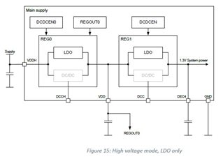
I am working on a project where the nRF52840 is used in USB powered mode. That means that it is normally supplied with 5V at the VDDH pin. In this case the nRF52840 generates internally its own VDD which is software adjustable and per default set to 1.8V according the datasheet.

But now the problem: the SWD programmer we want to use only supports 3.3V.

No matter which voltage I supply on the VDDH pin - before first programming the internal voltage regulator will generate 1.8V for VDD so that 3.3V at SWD pins would be much too high. I think the nRF52840 would get destroyed in this case.

So I got the idea to supply directly the VDD pins of the nRF52840 with an external 3.3V supply just for programming. But in normale voltage mode VDD and VDDH should be connected together according the datasheet - however they are not connected together in my design because in normal operation the nRF52840 will be supplied in high voltage mode with 5V at the VDDH pin.

Does anyone have an idea how to solve this problem?

What would happen if I just supply the VDD pins with 3.3V without connecting VDD and VDDH together?

Thank's a lot in advance for your help!

Cheers

Parents
  • Hi

    Where in the datasheet do you see that the nRF52840 generates its own VDD?

    Quote from the data sheets USB supply section: 
    "When using the USB peripheral, a 5 V USB supply needs to be provided on the VBUS pin. The USB peripheral has a dedicated internal voltage regulator for converting the VBUS supply to 3.3 V used by the USB signalling interface (D+ and D- lines, and pull-up on D+). The rest of the USB peripheral (USBD) is supplied through the main supply like any other on-chip feature. As a consequence, both VBUS and either VDDH or VDD supplies are required for USB peripheral operation."

    There shouldn't be a problem using a 3.3V specific debugger/programmer with the USB supply.

    Best regards,

    Simon

Reply
  • Hi

    Where in the datasheet do you see that the nRF52840 generates its own VDD?

    Quote from the data sheets USB supply section: 
    "When using the USB peripheral, a 5 V USB supply needs to be provided on the VBUS pin. The USB peripheral has a dedicated internal voltage regulator for converting the VBUS supply to 3.3 V used by the USB signalling interface (D+ and D- lines, and pull-up on D+). The rest of the USB peripheral (USBD) is supplied through the main supply like any other on-chip feature. As a consequence, both VBUS and either VDDH or VDD supplies are required for USB peripheral operation."

    There shouldn't be a problem using a 3.3V specific debugger/programmer with the USB supply.

    Best regards,

    Simon

Children
  • To me the following looked like I just need to connect VDDH and VBUS together and the internal REG0 stage provides the VDD supply. Am I wrong?

    5.3.1 Main supply:

    High voltage mode is entered when the supply voltage is only connected to the VDDH pin and the VDD pin
    is not connected to any voltage supply.

    5.3.1.1 Main voltage regulators:

    In high voltage mode, both regulator stages (REG0 and REG1) are used. The output voltage of
    REG0 can be configured in register REGOUT0 on page 45. This output voltage is connected to VDD and is
    the input voltage to REG1.

    5.3.1.4 Regulator configuration examples:

Related