This post is older than 2 years and might not be relevant anymore
More Info: Consider searching for newer posts

Exiting QSPI DPM mode when opening QSPI (memory has been put into DPM previously before QSPI was closed)

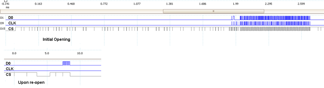
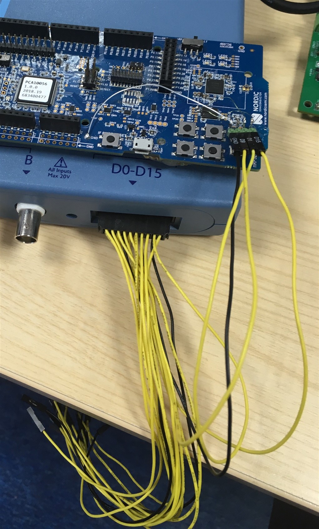
Using the nrfx_qspi driver, it is possible to put a QSPI memory into DPM to save power, this all works fine and well. We want to keep the memory in DPM when uninitiating the QSPI hardware on the nRF52840 which seems to work OK until we attempt to re-open the QSPI driver later and it causes a module reset because the nrfx_qspi_init function returns a timeout. Even toggling the CS line from high to low and back to high before opening doesn't seem to resolve the issue. The memory being used is a Macronix MX25R6435F (same as used on the nRF52840 development board). Is there a way to prevent this from failing?

  • I need a scope of the SPI lines from when you put the ext flash into DPM and uninitialize the driver, when you try to re-initialize the driver, as well as when you try to wake up the ext flash by toggling the CS line manually. 

  • Whilst getting a trace, I noticed that it seems that when it tries to re-open it, the module doesn't seem to be toggling the clock line, here is a trace of the initial opening and when I attempt to re-open it, the end of the top trace includes where it is being put into DPM:

    In the re-open, you can see where I drive the CS low then high to reset the module. For test purposes I am using nrf_delay_ms() with a period of 2ms for testing, the datasheet specifies a minimum of 35us so this should be more than sufficient.

    I can get more detailed scope traces if necessary, I stopped here as the clock line remaining low seems to be the issue.

  • The CS line seems to be pulled low at random intervals throughout the transaction.

    1. Is your CS line susceptible to EMI?

    2. Do you have anything else connected to your CS line? 

    3. Is this a measurement artifact?


    More detailed scopes might help, as well as the decoded data.

  • 1) With the oscilloscope cables attached yes, there are thin wires on the nRF52840 board connecting the QSPI pads to pin headers, and the pin headers are attached to the oscilloscope via long cables, see setup picture:

    So I put this down to noise from the surrounding environment (maybe 2.4GHz devices and sub-1GHz devices transmitting)

    2) No, nothing else is connected (this is being tested on an nRF52840-DK with wires added to the QSPI, no other changes to the hardware have been made)

  • It seems to be EMI induced into the attached logic analyzer probes. 

    Do you encounter this issue when the probes are removed? If yes, then I'll try to reproduce the issue and include the developers in my findings. Can you provide the code necessary to reproduce your issue?

Related