This post is older than 2 years and might not be relevant anymore
More Info: Consider searching for newer posts

NRF24LE1 how to set PWM frequency?

To what values should I set the PWMCON register to so that the PWM0 and PWM1 frequency is output at 20Khz with duty cycle varying between 1 to 2ms. Now specifically I am asking this after reading the data sheet because the tables mentioned are not clearing giving information. How do I decipher the table given here:
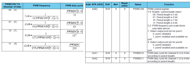
Please clearly disclose information in the data sheets. Also give an example to show how to set to particular frequency and pulse width.

Let me tell you how I decipher this as a newbie. Now CCLK is 16,000,000 for 16Mhz clock. I chose PWM0 as output so bit 0 is 1 and bit 1 is 0. Now I need to find out what PWMCON is so the formula for PWMCON for 20Khz PWM freq will be. (16000000/(255 x 20000))-1 = 160/51 -1 which is approximately 2. Hence PWMCON[5:2] will be 0010. There fore PWMCON will be 11001001 which is 0xC9. But this dint work when I put in this value for PWMCON as the servo did not rotate. Here is my code.

#include "reg24le1.h" // I/O header file for NRF24LE1
#include "hal_delay.h" // header file containing delay functions
 
// main function
void main()
{
int i = 0, j = 0; // loop variable
P0DIR = 0; // Port 0 as output
PWMCON = 0xc9; // enable PWM1
 
// infinte loop
while(1)
{
for(i= 180; i--; i > 0)
{
PWMDC0 = i ; // change duty cycle
delay_ms(10); // delay of 10 ms
}
 
 
}
 
}

Parents
  • One small mistake. The standard servo uses 50Hz PWM signal for control. Here is my new code to generate 50Hz wave using timers. Please correct it.

    #include "reg24le1.h" // I/O header file for NRF24LE1
    #include <stdlib.h> // standard library
    #include <string.h> // library containing string functions
    #include <stdio.h> // standard I/O library
     
    sfr16 DPTR = 0X82; // declare functional register DPTR
     
    // main function
    void main()
    {
     
    int i = 0;
    P0DIR = 0; // Port1 as output
     
    P03 = 0; // Pin 0 of Port 0 low
     
    EA = 1; // Enable global interrupt
    TMOD = 0X01 ; // timer0 in 16bit mode1
    TR0 = 1; // start timer
     
    // infinite loop
    while(1)
    {
    TH0 = 0; // initialise timer register upper byte
    TL0 = 0x43; // initialise timer register lower byte
    while(TF0 == 0); // wait for timer overflow flag
    TF0 = 0; // clear flag
    P03 =1; // make Pin0 of Port1 high
    TH0 = 0; // initialise timer register upper byte
    TL0 = 0; // initialise timer register lower byte
    while(TF0 == 0); // wait for timer overflow flag
    TF0 = 0; // clear flag
    P03 = 0; // make Pin0 of Port1 low
    }


    }

Reply
  • One small mistake. The standard servo uses 50Hz PWM signal for control. Here is my new code to generate 50Hz wave using timers. Please correct it.

    #include "reg24le1.h" // I/O header file for NRF24LE1
    #include <stdlib.h> // standard library
    #include <string.h> // library containing string functions
    #include <stdio.h> // standard I/O library
     
    sfr16 DPTR = 0X82; // declare functional register DPTR
     
    // main function
    void main()
    {
     
    int i = 0;
    P0DIR = 0; // Port1 as output
     
    P03 = 0; // Pin 0 of Port 0 low
     
    EA = 1; // Enable global interrupt
    TMOD = 0X01 ; // timer0 in 16bit mode1
    TR0 = 1; // start timer
     
    // infinite loop
    while(1)
    {
    TH0 = 0; // initialise timer register upper byte
    TL0 = 0x43; // initialise timer register lower byte
    while(TF0 == 0); // wait for timer overflow flag
    TF0 = 0; // clear flag
    P03 =1; // make Pin0 of Port1 high
    TH0 = 0; // initialise timer register upper byte
    TL0 = 0; // initialise timer register lower byte
    while(TF0 == 0); // wait for timer overflow flag
    TF0 = 0; // clear flag
    P03 = 0; // make Pin0 of Port1 low
    }


    }

Children
No Data
Related