This post is older than 2 years and might not be relevant anymore
More Info: Consider searching for newer posts

NRF24LE1 how to set PWM frequency?

To what values should I set the PWMCON register to so that the PWM0 and PWM1 frequency is output at 20Khz with duty cycle varying between 1 to 2ms. Now specifically I am asking this after reading the data sheet because the tables mentioned are not clearing giving information. How do I decipher the table given here:
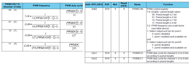
Please clearly disclose information in the data sheets. Also give an example to show how to set to particular frequency and pulse width.

Let me tell you how I decipher this as a newbie. Now CCLK is 16,000,000 for 16Mhz clock. I chose PWM0 as output so bit 0 is 1 and bit 1 is 0. Now I need to find out what PWMCON is so the formula for PWMCON for 20Khz PWM freq will be. (16000000/(255 x 20000))-1 = 160/51 -1 which is approximately 2. Hence PWMCON[5:2] will be 0010. There fore PWMCON will be 11001001 which is 0xC9. But this dint work when I put in this value for PWMCON as the servo did not rotate. Here is my code.

#include "reg24le1.h" // I/O header file for NRF24LE1
#include "hal_delay.h" // header file containing delay functions
 
// main function
void main()
{
int i = 0, j = 0; // loop variable
P0DIR = 0; // Port 0 as output
PWMCON = 0xc9; // enable PWM1
 
// infinte loop
while(1)
{
for(i= 180; i--; i > 0)
{
PWMDC0 = i ; // change duty cycle
delay_ms(10); // delay of 10 ms
}
 
 
}
 
}

Parents Reply Children
  • Is there a way that I can generate a way by software methods using timers. Generally in arduino they have a software library based PWM. They use timers. How can use timers to generate a 50Hz PWM?

  • We do not have a softPWM library available for the nRF24L-series devices. You'll have to manually use the timer to generate the pulse.


    Kind regards,

    Håkon

  • Here is a 15ms timer delay pulse. How do I change it to get a 20ms delay pulse and thus a 50Hz pulse?

    #include "reg24le1.h" // I/O header file for NRF24LE1
    #include <stdlib.h> // standard library
    #include <string.h> // library containing string functions
    #include <stdio.h> // standard I/O library
     
    sfr16 DPTR = 0X82; // declare functional register DPTR
     
    // main function
    void main()
    {
     
    int i = 0;
    P1DIR = 0; // Port1 as output
     
    P10 = 0; // Pin 0 of Port 1 low
     
    EA = 1; // Enable global interrupt
    TMOD = 0X01 ; // timer0 in 16bit mode1
    TR0 = 1; // start timer
     
    // infinite loop
    while(1)
    {
    TH0 = 0; // initialise timer register upper byte
    TL0 = 0; // initialise timer register lower byte
    while(TF0 == 0); // wait for timer overflow flag
    TF0 = 0; // clear flag
    P10 =1; // make Pin0 of Port1 high
    TH0 = 0; // initialise timer register upper byte
    TL0 = 0; // initialise timer register lower byte
    while(TF0 == 0); // wait for timer overflow flag
    TF0 = 0; // clear flag
    P10 = 0; // make Pin0 of Port1 low
    }
    }


  • Could you try this instead?

    #include <stdio.h>
    #include <stdint.h>
    #include "nrf24le1.h"
    
    void timer0_init(void)
    {
      TMOD |= 0x01; //16 bit timer
      TR0 = 1; //start timer
      ET0=1; //enable interrupt
    
    }
    
    
    void t0_interrupt(void) interrupt 1
    {       
      // Timer increments every 2*12 CPU clock cycles    
      // Timer starts counting down from 65535
      // 6666 * 1,5 us = 9999 us
      uint16_t timer_val = 0xFFFF - 6666;
      P10 ^= 1;
      TL0 = (uint8_t) (timer_val & 0xFF);
      TH0 = (uint8_t) ((timer_val >> 8) & 0xFF);
    }
    
    void main(void)
    {
        // Configure TXD pin as output.
        // P0.5, P0.3 and P1.0 are configured as outputs to make the example run on
        // either 24-pin, 32-pin or 48-pin nRF24LE1 variants.
        P0DIR = 0x00;
        P1DIR = 0x00;  
    
        CLKCTRL |=  0x1;
        // Enable global interrupts
        EA = 1;
        timer0_init();
        for(;;)
        {    
         
        }
    }

    This should generate a 50 hz pulse.

    Kind regards,

    Håkon

  • The code you provided above does not work. I found this. Will this code work? (It seemed to work some times).

    #include "reg24le1.h" // I/O header file for NRF24LE1
    #include "hal_delay.h" // header file containing delay functions


    #include "reg24le1.h" // I/O header file for NRF24LE1
    #include <stdlib.h> // standard library
    #include <string.h> // library containing string functions
    #include <stdio.h> // standard I/O library
    #include "hal_clk.h"
    //#include <reg51.h>
    #include "hal_rtc.h"
    // PWM_Pin
    sbit PWM_Pin = P0^6;		   // Pin P2.0 is named as PWM_Pin
    
    // Function declarations
    void cct_init(void);
    void InitTimer0(void);
    void InitPWM(void);
    
    // Global variables
    unsigned char PWM = 0;	  // It can have a value from 0 (0% duty cycle) to 255 (100% duty cycle)
    unsigned int temp = 0;    // Used inside Timer0 ISR
    
    // PWM frequency selector
    /* PWM_Freq_Num can have values in between 1 to 257	only
     * When PWM_Freq_Num is equal to 1, then it means highest PWM frequency
     * which is approximately 1000000/(1*255) = 3.9kHz
     * When PWM_Freq_Num is equal to 257, then it means lowest PWM frequency
     * which is approximately 1000000/(257*255) = 15Hz
     *
     * So, in general you can calculate PWM frequency by using the formula
     *     PWM Frequency = 1000000/(PWM_Freq_Num*255)
     */
    /*#define PWM_Freq_Num   78	 // Highest possible PWM Frequency
    
    
    void mcu_init(void)
    {  
    	hal_clk_set_freq(HAL_CLK_1MHZ);// = 4
      hal_clklf_set_source(HAL_CLKLF_XOSC16M_SYNTH);    // Synthesize 32 KHz from 16 MHz clock  
    	//hal_clklf_set_source(HAL_CLKLF_RCOSC32K);
    	hal_clk_set_freq(HAL_CLK_1MHZ);
      hal_rtc_set_compare_mode(HAL_RTC_COMPARE_MODE_0); // Use 32 KHz timer mode 0
      //hal_clk_regret_xosc16m_on(true);                  // Keep XOSC16M on in register retention
      //while (hal_clk_get_16m_source() != HAL_CLK_XOSC16M) {}
    }
    
    // Main Function
    int main(void)
    {
    	 hal_clk_set_freq(HAL_CLK_1MHZ);
       cct_init();   	       // Make all ports zero
       InitPWM();              // Start PWM
     
       PWM = 0;              // Make 50% duty cycle of PWM
    
       while(1)                // Rest is done in Timer0 interrupt
       {
    	 delay_ms(1);
    		 PWM++;
    		 if(PWM>=254)
    			 PWM=0;
    	 }
    }
    
    // Init CCT function
    void cct_init(void)
    {
    	P0 = 0x00;   
    	P1 = 0x00;   
    	P2 = 0x00;   
    	P3 = 0x00;  
    }
    
    // Timer0 initialize
    void InitTimer0(void)
    {
    	TMOD &= 0xF0;    // Clear 4bit field for timer0
    	TMOD |= 0x01;    // Set timer0 in mode 1 = 16bit mode
    	
    	TH0 = 0x00;      // First time value
    	TL0 = 0x00;      // Set arbitrarily zero
    	
    	ET0 = 1;         // Enable Timer0 interrupts
    	EA  = 1;         // Global interrupt enable
    	
    	TR0 = 1;         // Start Timer 0
    }
    
    // PWM initialize
    void InitPWM(void)
    {
    	PWM = 0;         // Initialize with 0% duty cycle
    	InitTimer0();    // Initialize timer0 to start generating interrupts
    					 // PWM generation code is written inside the Timer0 ISR
    }
    
    // Timer0 ISR
    void Timer0_ISR (void) interrupt 1   
    {
    	TR0 = 0;    // Stop Timer 0
    
    	if(PWM_Pin)	// if PWM_Pin is high
    	{
    		PWM_Pin = 0;
    		temp = (255-PWM)*PWM_Freq_Num;
    		TH0  = 0xFF - (temp>>8)&0xFF;
    		TL0  = 0xFF - temp&0xFF;	
    	}
    	else	     // if PWM_Pin is low
    	{
    		PWM_Pin = 1;
    		temp = PWM*PWM_Freq_Num;
    		TH0  = 0xFF - (temp>>8)&0xFF;
    		TL0  = 0xFF - temp&0xFF;
    	}
    
    	TF0 = 0;     // Clear the interrupt flag
    	TR0 = 1;     // Start Timer 0
    }

    Could you tell me what is wrong with my code and the code you gave me?

Related