Dear,
I am using nRF9160 DK, I want to use nRF9160 SIP to connect with another sensor ( UART /SPI)
Do you have any suggestions or examples?
Thanks,
Rgards
hng
Dear,
I am using nRF9160 DK, I want to use nRF9160 SIP to connect with another sensor ( UART /SPI)
Do you have any suggestions or examples?
Thanks,
Rgards
hng
Hi,
There's some generic UART and SPI samples available in my branch here:
https://github.com/Rallare/fw-nrfconnect-nrf/tree/nrf9160_samples/samples/nrf9160
Note that they only show how to setup the two peripherals, no handling of any external sensors.
Kind regards,
Håkon
Ja. Tusen takk Håkon, jeg vil prøve det
mvh
hng
Hi Håkon,
Thanks so much
I added "CONFIG_UART_1_NRF_UARTE=y" to prj.conf, and NO errors after boot
But I still confuse about PINs for UART1.
I am using nRF9160 DK, and in the nrf9160_pca10090.dts declares the pins for UART0 and UART1/*
* Copyright (c) 2017 Linaro Limited
* Copyright (c) 2018 Nordic Semiconductor ASA
*
* SPDX-License-Identifier: Apache-2.0
*/
/dts-v1/;
#include <nordic/nrf9160_xxaa.dtsi>
/ {
model = "Nordic PCA10090 Dev Kit";
compatible = "nordic,pca10090-dk", "nordic,nrf9160-xxaa";
chosen {
zephyr,console = &uart0;
zephyr,sram = &sram0;
zephyr,flash = &flash0;
};
aliases {
led0 = &led0;
led1 = &led1;
led2 = &led2;
led3 = &led3;
sw0 = &button2;
sw1 = &button3;
sw2 = &button0;
sw3 = &button1;
};
leds {
compatible = "gpio-leds";
led0: led_0 {
gpios = <&gpio0 2 GPIO_INT_ACTIVE_LOW>;
label = "Green LED 0";
};
led1: led_1 {
gpios = <&gpio0 3 GPIO_INT_ACTIVE_LOW>;
label = "Green LED 1";
};
led2: led_2 {
gpios = <&gpio0 4 GPIO_INT_ACTIVE_LOW>;
label = "Green LED 2";
};
led3: led_3 {
gpios = <&gpio0 5 GPIO_INT_ACTIVE_LOW>;
label = "Green LED 3";
};
};
buttons {
compatible = "gpio-keys";
button0: button_0 {
gpios = <&gpio0 8 GPIO_PUD_PULL_UP>;
label = "Switch 1";
};
button1: button_1 {
gpios = <&gpio0 9 GPIO_PUD_PULL_UP>;
label = "Switch 2";
};
button2: button_2 {
gpios = <&gpio0 6 GPIO_PUD_PULL_UP>;
label = "Push button 1";
};
button3: button_3 {
gpios = <&gpio0 7 GPIO_PUD_PULL_UP>;
label = "Push button 2";
};
};
sram0_bsd: memory@20010000 {
device_type = "memory";
compatible = "mmio-sram";
};
};
&uart0 {
status = "ok";
current-speed = <115200>;
tx-pin = <29>;
rx-pin = <28>;
rts-pin = <27>;
cts-pin = <26>;
};
&uart1 {
status = "ok";
current-speed = <115200>;
tx-pin = <1>;
rx-pin = <0>;
rts-pin = <14>;
cts-pin = <15>;
};
&gpiote {
status = "ok";
};
&gpio0 {
status = "ok";
};
&timer0 {
status = "ok";
};
&flash0 {
/*
* For more information, see:
* http://docs.zephyrproject.org/devices/dts/flash_partitions.html
*/
partitions {
compatible = "fixed-partitions";
#address-cells = <1>;
#size-cells = <1>;
boot_partition: partition@0 {
label = "mcuboot";
reg = <0x00000000 0x10000>;
};
slot0_partition: partition@10000 {
label = "image-0";
};
#if defined(CONFIG_ARM_TRUSTZONE_M)
slot0_ns_partition: partition@40000 {
label = "image-0-nonsecure";
};
#endif
slot1_partition: partition@80000 {
label = "image-1";
};
#if defined(CONFIG_ARM_TRUSTZONE_M)
slot1_ns_partition: partition@b0000 {
label = "image-1-nonsecure";
};
#endif
scratch_partition: partition@f0000 {
label = "image-scratch";
reg = <0x000f0000 0xa000>;
};
storage_partition: partition@fa000 {
label = "storage";
reg = <0x000fa000 0x00006000>;
};
};
};
#if defined(CONFIG_ARM_TRUSTZONE_M)
/ {
sram0_ns: memory@20020000 {
device_type = "memory";
compatible = "mmio-sram";
};
};
#endif
/* Include partition configuration file */
#include "nrf9160_pca10090_partition_conf.dts"
&uart1 pins are defined
and nRF9160 DK are designed compatible for Arduino UNO, so P0.00-RX and P0.01-TX
But, I still got NO output for uart1??
I need to read more about VCOM to understand clearly about this one
Thanks
Regards
hng
Hi,
In the "uart" sample, UARTE0 is used for printk() functions. When you changed it to use UART1 (which maps to UARTE1 peripheral), you are enabling two UART peripherals, which goes to two different pin-outs.
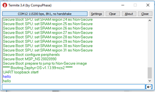
When you plug in the DK, it will give you 3 COM ports. Try opening them all with 115k2 baud, hit the reset-button and see which shows "UART loopback start!"
This is the terminal connected to UARTE0 peripheral.
The one that does not show any data is likely to be the one connected to the UARTE1 peripheral. Try sending any data to this one, and it should then be printed in the same terminal as "UART loopback start!" was shown in.
If you try to probe the P0.00 and P0.01 on the pinlist, they will not show anything, as these GPIOs are connected directly to the VCOM1 interface on the Segger IC.
Kind regards,
Håkon
Dear Håkon,
I am trying your suggestion,
If I use the UART0, just send and receive on UART0, it works,
the code:
#include <zephyr.h>
#include <misc/printk.h>
#include <uart.h>

static u8_t uart_buf[1024];

void uart_cb(struct device *x)
{
	uart_irq_update(x);
	int data_length = 0;

	if (uart_irq_rx_ready(x)) {
		data_length = uart_fifo_read(x, uart_buf, sizeof(uart_buf));
		uart_buf[data_length] = 0;
	}
	printk("%s", uart_buf);
}

void main(void)
{
	struct device *uart = device_get_binding("UART_0");

	uart_irq_callback_set(uart, uart_cb);
	uart_irq_rx_enable(uart);
	printk("UART loopback start!\n");
	while (1) {
		k_cpu_idle();

	}
}
I can receive the data I send at the same UART9 (COM12,115200bps,8N1,no handshake)

I tried to send data ("hello") and received "hello" from the same UART0
Then, I change to UART1 to send data:
struct device *uart = device_get_binding("UART_1");
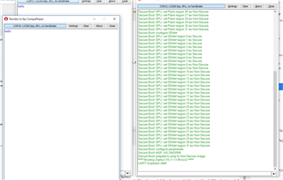
Then, reprogramme, then check: still NO data out on the UART0 (printk)

I tried to send data ("hello") from 2others COM, but UART0 didnt receive it.
What do you think?
Thanks so much
hng
Dear Håkon,
I fixed it now, I deleted the folder /build and rebuild again
I could redefine the pin for UART0/UART1 also.
Thanks
Regards,
hng
Hi,
That is strange. The only difference at my end is that I am using a .overlay file, but that should not have any impact, as its set in the main dts file.
Here's my .hex file, could you check if this one works at your end?
If that one does not work, it might be due to the nRF52 board controller firmware not being present. This can be downloaded from here (remember to switch SW5 into nRF52 position, and back again after programming):
https://www.nordicsemi.com/Software-and-Tools/Development-Kits/nRF9160-DK/Download#infotabs
*edit* race condition... You've already fixed the issue :)
Kind regards,
Håkon