This post is older than 2 years and might not be relevant anymore
More Info: Consider searching for newer posts

TWI manager interference with ANT

I am using the NRF52832 chip on a D52M M8 module, and SDK 15.2.

I have a number of sensors that I am communicating with over TWI using the TWI Manager on two separate channels.  The read transfers are scheduled on a timer running at a period of 240/32768.

Meanwhile I have an ANT broadcast master channel running at a period of 4096/32768.

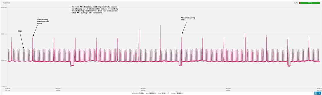
Running ANTWare in scan mode it skips 1-2 messages exactly once every 15 ANT cycles (every 1.89s).  This is very consistent so I believe the ANT message is not being sent.  The ANT ovserver callback function is running when I would expect though so the message is queued, just not sent.

For testing I am sending the time in microseconds in a test ANT packet, and so i can compare the ANT data with logs i create on the unit, in which i also log the twi status.  The attached excel shows this data.  Hopefully clear what everything means.  

This proves that when the ANT event coincides with a TWI transfer (i.e. in the period where a TWI transaction has been scheduled, but the callback hasn't returned yet) I still get log messages from my ANT callback, but no data is received in ANTWare.  I therefore believe the message is just not getting sent.

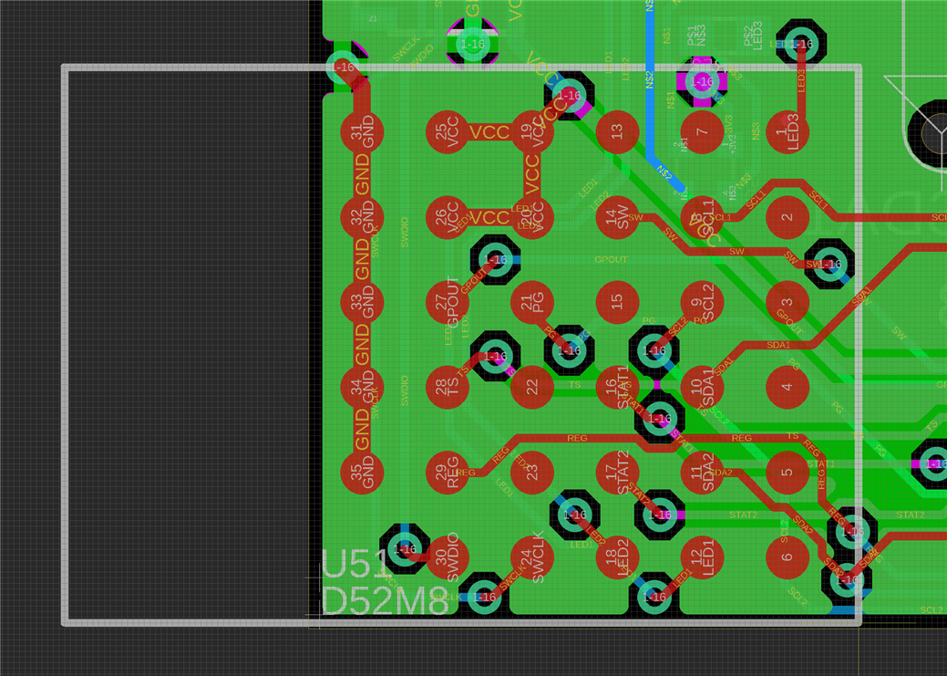
For the TWI channels i am using pins 2,3,4,5

From my previous support request ("Use of TWI manager with ANT") I understand that it should be possible to send ANT messages whilst a TWI transfer is in progress.  

I have followed the design guidelines in the module spec sheet.

Debugging I have gone as far as I think I am able to as I cannot look inside the softdevice to see what is going on.  Are there any suggestions on how to debug further, and/or ideas on what I might be doing wrong - sdk_config.h options etc?  

Parents
  • Hello,

    There was no attachment in this case, maybe you can upload again so I can take a look.

    In general what you describe should not be a problem, do you have access to a PPK so you can take a look at the current consumption trace in real-time, thereby compare the radio spikes with the twi spikes, and see how they overlap. If you have access to a nRF52-DK you may try the same also using two TWI interfaces. How does the ripple on VDD look like here? Have you tried to add more decoupling on VDD? Doe you have a picture of your hardware setup? What pull-up resistors do you have on the TWI pins?

    Best regards,
    Kenneth

  • Hi Kenneth,

    Thanks for the quick response.  Sorry about the attachment.  Here it is below.

    I don't have the PPK, but could get one, they seem quite cheap.  So far I have just run the power through a 10 ohm resistor and measured voltage drop to get an idea of current consumption, and logged with a digital oscilloscope.  I could easily do that and send across if you think helpful?

    The hardware is all on our custom boards, so I can't easily change decoupling. 

    Setting up on a DK (which I have by the way) is possible, but a little time consuming, and I only have a couple of sensors I could use (instead of the 4 on my boards).  But if it comes to it I could set something up to try and replicate our custom board setup as best I can.

    I can't easily show you the hardware setup, but could send you a schematic if that helps.  Or if you just want any details of decoupling etc then I can happily send over.

    We have no pull-up resistors on our boards, and are just using the internal pull-ups on the chip.

    Many thanks

    Barney

    TWI-ANT_Interference.xlsx

Reply
  • Hi Kenneth,

    Thanks for the quick response.  Sorry about the attachment.  Here it is below.

    I don't have the PPK, but could get one, they seem quite cheap.  So far I have just run the power through a 10 ohm resistor and measured voltage drop to get an idea of current consumption, and logged with a digital oscilloscope.  I could easily do that and send across if you think helpful?

    The hardware is all on our custom boards, so I can't easily change decoupling. 

    Setting up on a DK (which I have by the way) is possible, but a little time consuming, and I only have a couple of sensors I could use (instead of the 4 on my boards).  But if it comes to it I could set something up to try and replicate our custom board setup as best I can.

    I can't easily show you the hardware setup, but could send you a schematic if that helps.  Or if you just want any details of decoupling etc then I can happily send over.

    We have no pull-up resistors on our boards, and are just using the internal pull-ups on the chip.

    Many thanks

    Barney

    TWI-ANT_Interference.xlsx

Children
  • My main worry here is that the serial transfer is causing some noise in ground or VDD, so make sure that there is no split in ground layer, but a common solid ground connection to all ground pins and have a large decoupling capacitor close to the module (e.g. 4.7uF). Using external pull-up resistors may be something to consider (at least for test), since this will likely reduce noise on chip (at least I would think so). Having a 10ohm resistor trace measurement would be useful for confirm the issue, but I assume you are by default testing without the serial resistor, since a 10ohm resistor will cause significant noise on VDD. Please share schematic of your "motherboard" that the module is placed if possible.

    Best regards,
    Kenneth

  • Hi Kenneth,

    I bought a PPK (as seemed like a useful thing to have anyway) and have logged 15 ANT cycles which are in teh attached image.  It is a little hard to make out, but you can see the ANT spike moving relative to the TWI spikes so they overlap at some point during the 15 cycle period.  

    I guess the presence of a spike suggests the ANT message is in fact being sent, but something else is preventing reception, like TWI induced noise?

    I would be happy to share the board schematic, but there are certain things that are proprietary and we would rather not make public.  Is there a way I can send to you privately?

    I have two boards connected toggether with a ribbon cable.  On one is a voltage regulator feeding the chip and sensors, and on the other is the D52M module.  The second image below shows the board design around the module, and I think I have a sufficient ground connection.  I have no decoupling capacitor near the module though.  I had assumed Garmin would have put one on the module itself.  But you say this may is necessary.  Would it be worth me checking with Garmin directly?

    Many thanks

  • Hi,

    I suggest next step is a test that you try the two suggestions:

    1. Add a large decoupling capacitor (e.g. 4.7uF) close to the module.

    2. Use external pull ups on TWI (possible on the other board in this case).

    bgarrood said:
    I guess the presence of a spike suggests the ANT message is in fact being sent, but something else is preventing reception, like TWI induced noise?

    I agree, the TWI likely impact the carrier or modulation here in such a way that the packet is no longer received on the receiver. I think part of the problem may be the LDO is placed on a different board. 

    bgarrood said:
    On one is a voltage regulator feeding the chip and sensors, and on the other is the D52M module.

    Not sure if I understood this, isn't the "chip" the same as D52M module?

    Best regards,
    Kenneth

  • Hi,


    Thank you for that.  Yes, poor wording by me, the LDO is on a different board to the D52M is all I am saying here.

    I have logged a support request with Garmin and so will wait to see what they say.  Based on that I will do some testing and report back.

    Thank you.

  • Hello.  I thought I would give an update.

    Garmin have no specific recommendations but concurred with you Kenneth.  They also suggested adding 22pF capacitors on the twi lines to attenuate nosie which could interfere with the radio.

    I have done some more tests and discovered the following:

    • Noise on VCC-GND is very low, and I see no signs of noise at anything around the 400kHz TWI frequency (it was this noise I expected to see).  My oscilloscope only has a sensitivity of 10MHz so wouldn't see anything in the GHz range.
    • Changing the code to just communicate with a single sensor on the same board as the D52 module I still see the drop-out issue. 
    • With a single sensor, the twi transaction is very quick, 200us, and in this case I never see the ANT event occurring during a twi transaction.  However I still see the dropouts when the ANT event occurs right next to (within a few microseconds) of the twi transaction finishing.
    • Powering a single board with the D52 module and sensors (so no regulators or ribbon cable) directly from a bench power supply via soldered leads I still get the dropouts.
    • Soldering leads to a breadboard from the SCL/SDA nets I have added in external pull-ups but still get the drop-outs.
    • I have cut up one of our boards to remove the D52 module and wired the sensors directly to a D52 dev kit module.  Running identical code (even using same pins on both D52 M8 and D52 dev kit modules) I get no dropouts with the dev kit.
    • Back to our boards: we have two joined by a ribbon cable.  One has the D52 module and sensors operating on TWI channel 0.  The other has the regulators and sensors operating on channel 1-both boards have the same sensors on them.  If I just run the sensors on channel 1 then I get no dropouts.  This is interesting  - the sensors and D52 module have separate power supply lines coming across the ribbon cable but share a ground.  Perhaps this is the cause of the issue, some noise on the ground plane?  Since we still get the dropouts using the single board with bench power supply I think we can rule out the ribbon cable.  Problem is isolated to whats going on on the board itself.
    • We have therefore isolated the problem to the board layout.  I think likely as we suspected electrical noise generated by TWI transactions is interfering with the radio.

    If you have any other suggestions based on thsi please let me know.  As the problem is isolated to the board, the only way to test fixes is to make new boards, which is expensive, so I want to be sure to get it right!

    Many thanks.

Related