This post is older than 2 years and might not be relevant anymore
More Info: Consider searching for newer posts

nRF52 wakeup time

Hi,

what is the typical or max wake up time of the nRF52 from the RTC or GPIOTE irq (when configured as sense for low level input)?

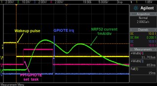
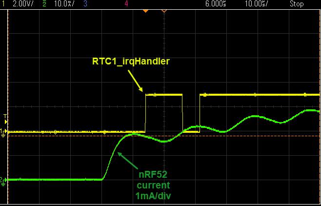
In my setup, I see a wakeup time of ~13usec from the moment that the nRF52 current consumption is increasing, till the time the RTC irq handler is running.

RTC is running from an external crystal.

Normally I would expect the following wakeup delays till the start of RTC irq handler:

tSTART_HFINT Startup time: 3us

tIDLE2CPU Time from IDLE to CPU execute: 3us

What is the reason that I see 13us and not 6us till the RTC handler starts to execute code?

The wakup time from an external GPIO sense low event that I measure is ~16us.

Regards

Thanassis

Parents
  • Hi

    What is causing the extra time before the IRQ handler kicks in is likely that the GPIO driver causes some delay going through overheads. You can try writing to NRF_GPIO directly instead, to avoid any unnecessary calls. The nRF goes to sleep as soon as it is done, but you are measuring over a decoupling capacitor, which holds on to the voltage for some time, which is why you see the curve.

    I suggest you take a look at the PPI, as I suspect it may suit your application, seeing as it doesn't depend on the CPU. I don't know which chip you are using so I attached the link to the nRF52840 PPI, if you want to use it please make sure to read the correct PS.

    Best regards,

    Simon

  • Hi,

    the CPU that I use is the nRF52832_xxAA.

    I will try to write direct to the NRF_GPIO to see if it has any measurable effect.

    I think your suggestion to use the NRF_GPIOTE->EVENTS_PORT and feed it to the

    PPI to toggle a GPIO pin, it will show the accurate wakeup timing.

    I will let you know about the results.

    Best Regards

    Thanassis

  • Hi,

    using the PPI & GPIOTE to set a pin output, shows that the nRF52 is setting the output 3us after the wakeup pulse.

    The time for the GPIOTE irq handler to kick is ~12us.

    The code used to set the pin output from the GPIOTE PORT event is:

        // ppi init - connect GPIOTE irq event to the GPIO_PPI_IRQ_PIN 
        nrf_ppi_channel_endpoint_setup(NRF_PPI_CHANNEL0, (uint32_t)&NRF_GPIOTE->EVENTS_PORT, (uint32_t)&NRF_GPIOTE->TASKS_SET[0]);
        nrf_ppi_channel_enable(NRF_PPI_CHANNEL0);
        
        // configure PPI GPIOTE pin
        nrf_gpiote_event_configure(0, GPIO_PPI_IRQ_PIN, NRF_GPIOTE_POLARITY_LOTOHI);
        nrf_gpiote_task_enable(0);
    

    Best Regards

    Thanassis

Reply
  • Hi,

    using the PPI & GPIOTE to set a pin output, shows that the nRF52 is setting the output 3us after the wakeup pulse.

    The time for the GPIOTE irq handler to kick is ~12us.

    The code used to set the pin output from the GPIOTE PORT event is:

        // ppi init - connect GPIOTE irq event to the GPIO_PPI_IRQ_PIN 
        nrf_ppi_channel_endpoint_setup(NRF_PPI_CHANNEL0, (uint32_t)&NRF_GPIOTE->EVENTS_PORT, (uint32_t)&NRF_GPIOTE->TASKS_SET[0]);
        nrf_ppi_channel_enable(NRF_PPI_CHANNEL0);
        
        // configure PPI GPIOTE pin
        nrf_gpiote_event_configure(0, GPIO_PPI_IRQ_PIN, NRF_GPIOTE_POLARITY_LOTOHI);
        nrf_gpiote_task_enable(0);
    

    Best Regards

    Thanassis

Children
No Data
Related