Dear,
I tried the same code on :
https://devzone.nordicsemi.com/f/nordic-q-a/43774/simple-gpio-example---nrf9160-dk/173275#173275
and my code:
#include <zephyr.h>
#include <device.h>
#include <gpio.h>
/* 1000 msec = 1 sec */
#define SLEEP_TIME 5000
void main(void)
{
int cnt = 0;
struct device *dev;
dev = device_get_binding("GPIO_0");
/* Set LED pin as output */
gpio_pin_configure(dev, 2, GPIO_DIR_OUT); //p0.03 == LED2
gpio_pin_configure(dev, 3, GPIO_DIR_OUT); //p0.04 == LED3
gpio_pin_configure(dev, 4, GPIO_DIR_OUT); //p0.03 == LED2
gpio_pin_configure(dev, 5, GPIO_DIR_OUT); //p0.04 == LED3
gpio_pin_configure(dev, 17, GPIO_DIR_OUT); //p0.17
gpio_pin_configure(dev, 18, GPIO_DIR_OUT); //p0.18
gpio_pin_configure(dev, 19, GPIO_DIR_OUT); //p0.19
while (1) {
/* Set pin to HIGH/LOW every 1 second */
gpio_pin_write(dev, 2, cnt % 2); //p0.03 == LED2
gpio_pin_write(dev, 3, cnt % 2); //p0.04 == LED3
gpio_pin_write(dev, 4, cnt % 2); //p0.03 == LED2
gpio_pin_write(dev, 5, cnt % 2); //p0.04 == LED3
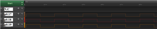
gpio_pin_write(dev, 17, cnt % 2); //p0.17 Toggling pin 17
gpio_pin_write(dev, 18, cnt % 2); //18
gpio_pin_write(dev, 19, cnt % 2); //19
cnt++;
k_sleep(SLEEP_TIME);
}
}
The Led1,2,3,4 will on/off in 5s, but P0.17 P0.18 P0.19 didnt change !!
Something else do we need to setup?
I check my dts file:
/*
 * Copyright (c) 2017 Linaro Limited
 * Copyright (c) 2018 Nordic Semiconductor ASA
 *
 * SPDX-License-Identifier: Apache-2.0
 */

/dts-v1/;
#include <nordic/nrf9160_xxaa.dtsi>

/ {
	model = "Nordic PCA10090 Dev Kit";
	compatible = "nordic,pca10090-dk", "nordic,nrf9160-xxaa";

	chosen {
		zephyr,console = &uart0;
                zephyr,sram = &sram0;
		zephyr,flash = &flash0;
	};

	aliases {
		led0 = &led0;
		led1 = &led1;
		led2 = &led2;
		led3 = &led3;
		sw0 = &button2;
		sw1 = &button3;
		sw2 = &button0;
		sw3 = &button1;
	};

	leds {
		compatible = "gpio-leds";
		led0: led_0 {
			gpios = <&gpio0 2 GPIO_INT_ACTIVE_LOW>;
			label = "Green LED 0";
		};
		led1: led_1 {
			gpios = <&gpio0 3 GPIO_INT_ACTIVE_LOW>;
			label = "Green LED 1";
		};
		led2: led_2 {
			gpios = <&gpio0 4 GPIO_INT_ACTIVE_LOW>;
			label = "Green LED 2";
		};
		led3: led_3 {
			gpios = <&gpio0 5 GPIO_INT_ACTIVE_LOW>;
			label = "Green LED 3";
		};
	};

	buttons {
		compatible = "gpio-keys";
		button0: button_0 {
			gpios = <&gpio0 8 GPIO_PUD_PULL_UP>;
			label = "Switch 1";
		};
		button1: button_1 {
			gpios = <&gpio0 9 GPIO_PUD_PULL_UP>;
			label = "Switch 2";
		};
		button2: button_2 {
			gpios = <&gpio0 6 GPIO_PUD_PULL_UP>;
			label = "Push button 1";
		};
		button3: button_3 {
			gpios = <&gpio0 7 GPIO_PUD_PULL_UP>;
			label = "Push button 2";
		};
	};

	sram0_bsd: memory@20010000 {
		device_type = "memory";
		compatible = "mmio-sram";
	};
};

&uart0 {
	status = "ok";
	current-speed = <9600>;
	tx-pin = <10>;
	rx-pin = <11>;
	rts-pin = <27>;
	cts-pin = <26>;
};

&uart1 {
	status = "ok";
	current-speed = <9600>;
	tx-pin = <12>;
	rx-pin = <13>;
	rts-pin = <14>;
	cts-pin = <15>;
};

&gpiote {
	status = "ok";
};

&gpio0 {
	status = "ok";
};

&timer0 {
	status = "ok";
};

&flash0 {
	/*
	 * For more information, see:
	 * http://docs.zephyrproject.org/devices/dts/flash_partitions.html
	 */
	partitions {
		compatible = "fixed-partitions";
		#address-cells = <1>;
		#size-cells = <1>;

		boot_partition: partition@0 {
			label = "mcuboot";
			reg = <0x00000000 0x10000>;
		};
		slot0_partition: partition@10000 {
			label = "image-0";
		};
#if defined(CONFIG_ARM_TRUSTZONE_M)
		slot0_ns_partition: partition@40000 {
			label = "image-0-nonsecure";
		};
#endif
		slot1_partition: partition@80000 {
			label = "image-1";
		};
#if defined(CONFIG_ARM_TRUSTZONE_M)
		slot1_ns_partition: partition@b0000 {
			label = "image-1-nonsecure";
		};
#endif
		scratch_partition: partition@f0000 {
			label = "image-scratch";
			reg = <0x000f0000 0xa000>;
		};

		storage_partition: partition@fa000 {
			label = "storage";
			reg = <0x000fa000 0x00006000>;
		};
	};
};

#if defined(CONFIG_ARM_TRUSTZONE_M)
/ {
	sram0_ns: memory@20020000 {
		device_type = "memory";
		compatible = "mmio-sram";
	};
};
#endif

/* Include partition configuration file */
#include "nrf9160_pca10090_partition_conf.dts"
the define for gpio;
&gpiote {
status = "ok";
};
&gpio0 {
status = "ok";
};
is it correct?
Plz tell me where is wrong on my code
Thanks
Regards,
hng