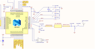
As long as the amplifier has 50 ohm in and output, you can insert it between the matching network and the antenna. Alternatively, connect the PA input to the test connector on the PCB and use an external antenna.
Hello,
If I correctly understood your input then please confirm me below interface of Amplifier is correct.
After ANT pin below is the sequence:
C2-L2 filter
50 OHM trace
RF Amplifier (CC2595)
50 OHM trace
C1-L1 filter as shown.
Could you please suggest the ceramic chip Antenna suitable for this as power will be more than +4dB after RF Amplifier?
Can I used the same values of L and C for filter purpose as given is Thingy hardware?
Could you please share if similar design for nRF52832/810 if available?
Could you please suggest if any other RF Amplifier which will be suitable for this device?
Yes, the schematic is correct.
Any chip antenna should be able to handle this kind of power.
The antenna tuning components are dependent on your design will most probably change, unless you make a 1:1 copy of Thingy. Things like size of the PCB and the ground plane have impact.
The design will be identical with any other device. Just replace the matching network (L1/C3) with the values from the device's reference schematic.
The choice of amplifier depends on how much output power you need. Note that there a regulatory limits in difference parts of the world you need to be aware of. In Europe for instance, the limit it 10 dBm.
Thank you for inputs. Majorly we are targeting India region only and as per my knowledge +12dB is OK. Also depending on input power from MCU, amplifier will generate the dB. 832/810 both can provide the variable dB and so we can adjust the amplifier output. Is it correct ?
The output power can be set in 4 dB steps, any finer adjustment has to be done with the PA.