
How can I port nRF51822 SDK examples made for the development kit (in the NRF6310 folder) to the nRF51822 evaluation kit?
How can I port nRF51822 SDK examples made for the development kit (in the NRF6310 folder) to the nRF51822 evaluation kit?
The difference between the nRF51822 development kit and nRF51822 evaluation kit is explained on this thread.
The different examples in the nRF51 SDK are either ported for the evaluation kit or the development kit. However, there is basically almost no difference between the examples for the evaluation kit and the development kit. The main difference is the mapping of LEDs and Buttons on the two kits. The LEDs and Buttons map to different GPIO pins on the two kits. Additionally, the evaluation kit has two LEDs and two buttons, while the development kit has 8 LEDs and 8 buttons.
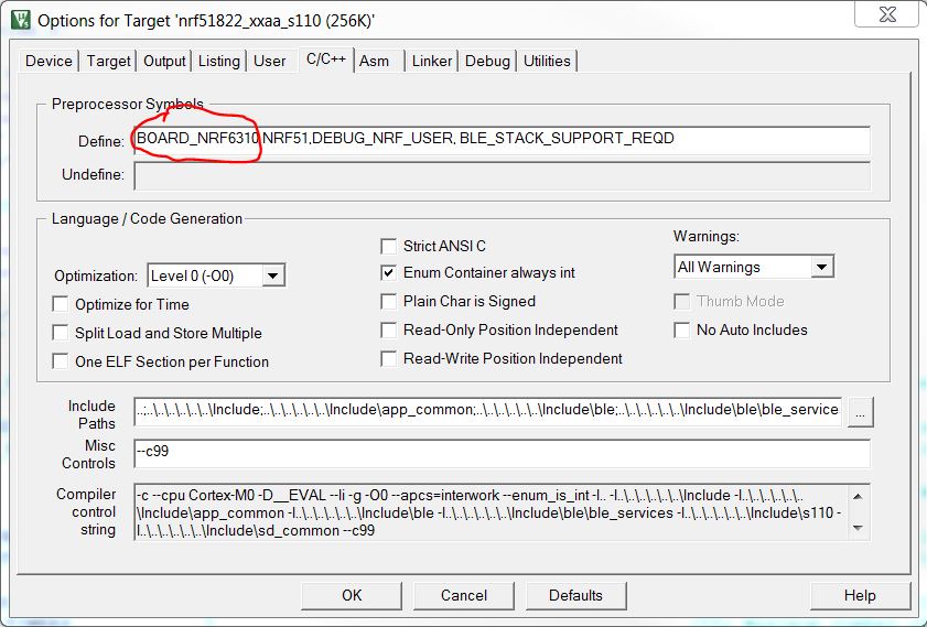
To make the development kit examples (in the NRF6310 folder in the SDK) compatible with the PCA10001 evaluation kit, replace the BOARD_NRF6310 constant with BOARD_PCA10001 constant in the compiler defines in KEIL, see picture below. That will remap LEDs and buttons to the evaluation kit (PCA10001). This will however only map LED_0, LED_1, BUTTON_0 and BUTTON_1 to the evaluation board, since it only has two leds and two buttons. If the example for the development kit (NRF6310) is using more than two leds and/or two buttons, then you will get a compile error when compiling for the evaluation board. You must then manually comment out all usage of leds and buttons in the example that are not LED_0, LED_1, BUTTON_0 or BUTTON_1.
The difference between the nRF51822 development kit and nRF51822 evaluation kit is explained on this thread.
The different examples in the nRF51 SDK are either ported for the evaluation kit or the development kit. However, there is basically almost no difference between the examples for the evaluation kit and the development kit. The main difference is the mapping of LEDs and Buttons on the two kits. The LEDs and Buttons map to different GPIO pins on the two kits. Additionally, the evaluation kit has two LEDs and two buttons, while the development kit has 8 LEDs and 8 buttons.
To make the development kit examples (in the NRF6310 folder in the SDK) compatible with the PCA10001 evaluation kit, replace the BOARD_NRF6310 constant with BOARD_PCA10001 constant in the compiler defines in KEIL, see picture below. That will remap LEDs and buttons to the evaluation kit (PCA10001). This will however only map LED_0, LED_1, BUTTON_0 and BUTTON_1 to the evaluation board, since it only has two leds and two buttons. If the example for the development kit (NRF6310) is using more than two leds and/or two buttons, then you will get a compile error when compiling for the evaluation board. You must then manually comment out all usage of leds and buttons in the example that are not LED_0, LED_1, BUTTON_0 or BUTTON_1.

To add to above, if you are using eclipse gcc you just have to change it in the makefile and fix the compile error. Also have to check for where LCD display stuff is also. This depend on project. In blue_app_hrs_c the main.c has a #define to allow LCD display.
I tried above guidelines, but still hyperterminal does not show anything. Although it seems like connection has built up between slave and central. can i extract main.c from hex of file that shows output on terminal?