Hey everyone, I'm having an issue communicating with a QSPI flash on a custom development board, using the nRF52840. The flash is a Winbond W25Q16JVSSIQ. Schematic and pins used are the same as the nRF52840 DK and as far as I can tell, the flash I'm using uses the same commands as the default defines. I've been at this for a whole day and don't have much hair left to pull out. I've checked and double checked the hardware and it looks good to me, I have connectivity from the module to the flash.
The device seems to initialize ok, there are no errors returned from nrfx_qspi_init, but I can't get nrfx_qspi_cinstr_xfer to return anything other than 0... I've tried every combo of 'length' and tx/rx string lengths I can come up with, I just can't wrap my head around how this is supposed to work. I also never get a finished flag when doing nrfx_qspi_write. If I just don't wait, nrfx_qspi_read gives me a BUSY error.
Any help anyone can offer is much appreciated. I fought my way though getting an ADC, UART, and BLE set up, but this is killing me!
Here's my defines and function:
#define QSPI_STD_CMD_MFG_DEV_ID 0x94
#define QSPI_STD_CMD_WRSR   0x01
#define QSPI_STD_CMD_RSTEN  0x66
#define QSPI_STD_CMD_RST    0x99

#define QSPI_RX_BUFFER_SIZE 10
#define SAMPLES_IN_BUFFER   10    //used to buffer adc readings, and also to size the qspi tx buffer

static volatile bool m_qspi_finished = false;
static uint8_t m_qspi_buffer_tx[SAMPLES_IN_BUFFER];
static uint8_t m_qspi_buffer_rx[QSPI_RX_BUFFER_SIZE];    //this will also be the BLE transmit package size/2
static void qspi_handler(nrfx_qspi_evt_t event, void * p_context)
{
    UNUSED_PARAMETER(event);
    UNUSED_PARAMETER(p_context);
    m_qspi_finished = true;
}
static void qspi_init(void){

    uint32_t err_code;
    static uint8_t temp_rx_buf[9];
    static uint8_t temp_tx_buf[9];

    nrfx_qspi_config_t config = NRFX_QSPI_DEFAULT_CONFIG;

    err_code = nrfx_qspi_init(&config, qspi_handler, NULL);
    APP_ERROR_CHECK(err_code);

    nrf_qspi_cinstr_conf_t cinstr_cfg = {
        .opcode    = QSPI_STD_CMD_MFG_DEV_ID,
        .length    = NRF_QSPI_CINSTR_LEN_9B,
        .io2_level = true,
        .io3_level = true,
        .wipwait   = true,
        .wren      = true
    };

    err_code = nrfx_qspi_cinstr_xfer(&cinstr_cfg, temp_tx_buf, temp_rx_buf);
    APP_ERROR_CHECK(err_code);

    printf("qspi_init mfg id: %d device id: %d\r\n", temp_rx_buf[7], temp_rx_buf[8]);

    temp_tx_buf[0] = 69;

    err_code = nrfx_qspi_write(temp_tx_buf, 1, 0);
    printf("nrfx_qspi_write err_code %d\r\n", err_code);
    //APP_ERROR_CHECK(err_code);
    while (!m_qspi_finished);
    m_qspi_finished = false;

    err_code = nrfx_qspi_read(temp_rx_buf, 1, 0);
    printf("nrfx_qspi_read err_code %d\r\n", err_code);
    //APP_ERROR_CHECK(err_code);
    while (!m_qspi_finished);
    m_qspi_finished = false;

    printf("Test Data: %d \r\n", temp_rx_buf[0]);

}
Here's the sdk_config lines:
// <e> NRFX_QSPI_ENABLED - nrfx_qspi - QSPI peripheral driver
//==========================================================
#ifndef NRFX_QSPI_ENABLED
#define NRFX_QSPI_ENABLED 1
#endif
// <o> NRFX_QSPI_CONFIG_SCK_DELAY - tSHSL, tWHSL and tSHWL in number of 16 MHz periods (62.5 ns).  <0-255>


#ifndef NRFX_QSPI_CONFIG_SCK_DELAY
#define NRFX_QSPI_CONFIG_SCK_DELAY 1
#endif

// <o> NRFX_QSPI_CONFIG_XIP_OFFSET - Address offset in the external memory for Execute in Place operation.
#ifndef NRFX_QSPI_CONFIG_XIP_OFFSET
#define NRFX_QSPI_CONFIG_XIP_OFFSET 0
#endif

// <o> NRFX_QSPI_CONFIG_READOC  - Number of data lines and opcode used for reading.

// <0=> FastRead
// <1=> Read2O
// <2=> Read2IO
// <3=> Read4O
// <4=> Read4IO

#ifndef NRFX_QSPI_CONFIG_READOC
#define NRFX_QSPI_CONFIG_READOC 4
#endif

// <o> NRFX_QSPI_CONFIG_WRITEOC  - Number of data lines and opcode used for writing.

// <0=> PP
// <1=> PP2O
// <2=> PP4O
// <3=> PP4IO

#ifndef NRFX_QSPI_CONFIG_WRITEOC
#define NRFX_QSPI_CONFIG_WRITEOC 2
#endif

// <o> NRFX_QSPI_CONFIG_ADDRMODE  - Addressing mode.

// <0=> 24bit
// <1=> 32bit

#ifndef NRFX_QSPI_CONFIG_ADDRMODE
#define NRFX_QSPI_CONFIG_ADDRMODE 0
#endif

// <o> NRFX_QSPI_CONFIG_MODE  - SPI mode.

// <0=> Mode 0
// <1=> Mode 1

#ifndef NRFX_QSPI_CONFIG_MODE
#define NRFX_QSPI_CONFIG_MODE 0
#endif

// <o> NRFX_QSPI_CONFIG_FREQUENCY  - Frequency divider.

// <0=> 32MHz/1
// <1=> 32MHz/2
// <2=> 32MHz/3
// <3=> 32MHz/4
// <4=> 32MHz/5
// <5=> 32MHz/6
// <6=> 32MHz/7
// <7=> 32MHz/8
// <8=> 32MHz/9
// <9=> 32MHz/10
// <10=> 32MHz/11
// <11=> 32MHz/12
// <12=> 32MHz/13
// <13=> 32MHz/14
// <14=> 32MHz/15
// <15=> 32MHz/16

#ifndef NRFX_QSPI_CONFIG_FREQUENCY
#define NRFX_QSPI_CONFIG_FREQUENCY 15
#endif

// <s> NRFX_QSPI_PIN_SCK - SCK pin value.
#ifndef NRFX_QSPI_PIN_SCK
#define NRFX_QSPI_PIN_SCK 19
#endif

// <s> NRFX_QSPI_PIN_CSN - CSN pin value.
#ifndef NRFX_QSPI_PIN_CSN
#define NRFX_QSPI_PIN_CSN 17
#endif

// <s> NRFX_QSPI_PIN_IO0 - IO0 pin value.
#ifndef NRFX_QSPI_PIN_IO0
#define NRFX_QSPI_PIN_IO0 20
#endif

// <s> NRFX_QSPI_PIN_IO1 - IO1 pin value.
#ifndef NRFX_QSPI_PIN_IO1
#define NRFX_QSPI_PIN_IO1 21
#endif

// <s> NRFX_QSPI_PIN_IO2 - IO2 pin value.
#ifndef NRFX_QSPI_PIN_IO2
#define NRFX_QSPI_PIN_IO2 22
#endif

// <s> NRFX_QSPI_PIN_IO3 - IO3 pin value.
#ifndef NRFX_QSPI_PIN_IO3
#define NRFX_QSPI_PIN_IO3 23
#endif

// <o> NRFX_QSPI_CONFIG_IRQ_PRIORITY  - Interrupt priority

// <0=> 0 (highest)
// <1=> 1
// <2=> 2
// <3=> 3
// <4=> 4
// <5=> 5
// <6=> 6
// <7=> 7

#ifndef NRFX_QSPI_CONFIG_IRQ_PRIORITY
#define NRFX_QSPI_CONFIG_IRQ_PRIORITY 6
#endif

// </e>
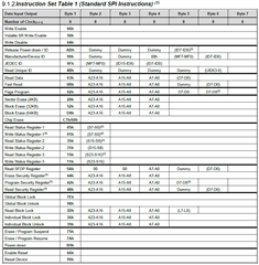
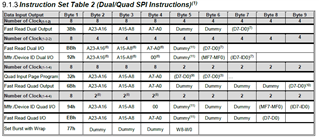
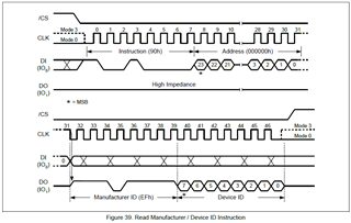
Here are the command tables from the Flash data sheet: