This post is older than 2 years and might not be relevant anymore
More Info: Consider searching for newer posts

DTM unmodulated carrier signal spectrum

Hello dear Nordic community,

currently I am working on the NRF51822 Direct test mode (DTM). I tested the ble_app_dtm example and it works fine for me. This means I can send commands according to Bluetooth specification Ver 4.0, Vol 6, part F and receive events.

First test was to send an unmodulated carrier signal on channel 1 (f=2404MHz). I sent through the UART interface 0x81 0x00 (This means CMD=Transmitter test, FREQUENCY=1, LENGTH=0, PKT=0, see 3.3.2 in Bluetooth specification Ver 4.0, Vol 6, part F) The spectrum I get is shown in the picture below.

image description

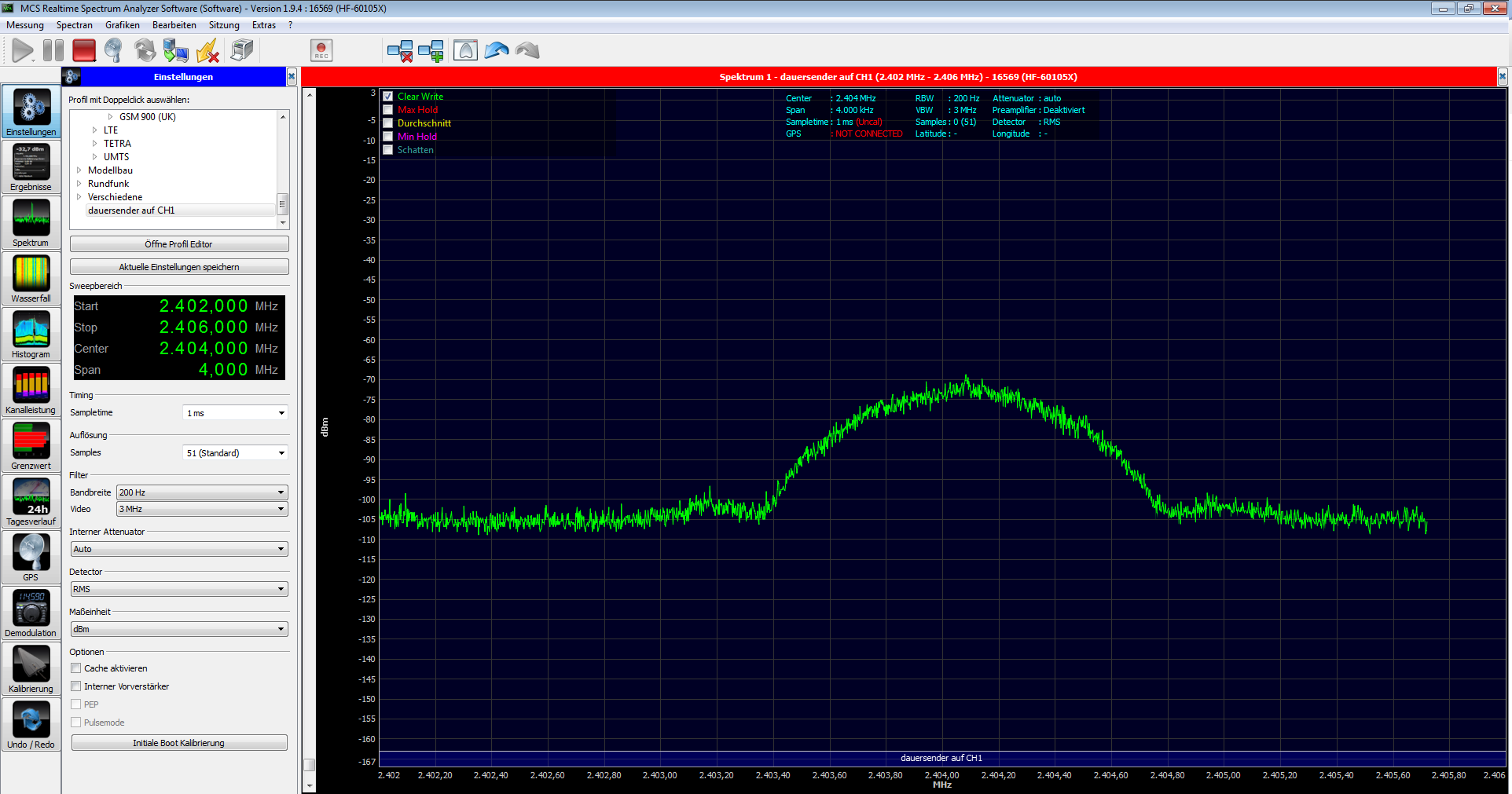
The first thing I notice is that the spectrum is ca. 1MHz wide. I expected to see Dirac like (more narrow) spectrum at f=2404MHz. Is my configuration for unmodulated carrier signal(0x81 0x00) correct? Is the spectrum in the picture correct?

Second test I performed was to send 0x81 0x96 (CMD=Transmitter test, FREQUENCY=1, LENGTH=37 octets, PKT = 10101010 Packet Payload). The spectrum was the same as for 0x81 0x00. I expected to see to symmetric peaks around the carrier frequency (f=2404MHz) one for the zero frequency and one for the one frequency. Why the spectrum remains the same? Is the configuration 0x81 0x96 correct for constant signal like 10101010101010101....

Best regards,

Stefan

Parents
  • How are you connecting the output of the nRF51 to the input of the spectrum analyzer? The peak of what you have measured is about -70 dBm and that is really really low. I don't know how you have connected them, so it's difficult to suggest what to do differently than to make sure that your soldering (if measured conducted) is done properly or if you are doing it radiated that the antennas are correct.

    To rule out the factor of sending the correct DTM commands, please have a look at the radio_test_example in the SDK. You can configure the radio into various test modes by similar means of the DTM modes, but the radio_test_example code example is easier to understand and might be easier to get going and to make sure that you actually are looking at the right place.

    You should also widen your span on the spectrum just to be sure that you haven't configured the test mode on a channel outside the 4 MHz span. For initial test/debugging, set the span to be 100 MHz with center at 2.44 GHz. If there's anything present from the BLE radio, you'll see it right away and could then zoom in to get the details.

Reply
  • How are you connecting the output of the nRF51 to the input of the spectrum analyzer? The peak of what you have measured is about -70 dBm and that is really really low. I don't know how you have connected them, so it's difficult to suggest what to do differently than to make sure that your soldering (if measured conducted) is done properly or if you are doing it radiated that the antennas are correct.

    To rule out the factor of sending the correct DTM commands, please have a look at the radio_test_example in the SDK. You can configure the radio into various test modes by similar means of the DTM modes, but the radio_test_example code example is easier to understand and might be easier to get going and to make sure that you actually are looking at the right place.

    You should also widen your span on the spectrum just to be sure that you haven't configured the test mode on a channel outside the 4 MHz span. For initial test/debugging, set the span to be 100 MHz with center at 2.44 GHz. If there's anything present from the BLE radio, you'll see it right away and could then zoom in to get the details.

Children
No Data
Related