This post is older than 2 years and might not be relevant anymore
More Info: Consider searching for newer posts

How optimize high current consumption in sleep mode using nRF52840?

Hello to all,

We have developed our application & the following platform we are using:

  • SDK 15.0, Segger IDE on windows PC
  • Softdevice version is 6.0.0
  • Hardware version nRF52840 SoC.
  • Our product is battery operated, so high power consumption is serious an issue for us.

In our application we have used ble_app_uart example with SAADC because our sensor is analog. We also made custom PCB using nRF52840 and it working well not an issue. But our problem is very too much high current consumption is sleep mode means system OFF mode.

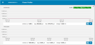
Here is below measured analysis with the help of Nordic Power Profile kit:

  1. The average current consumption while advertising is 962uA - 1.62mA I think this is OK.
  2. The average current consumption when sensor device enter into sleep mode is 562uA (Which is very high)

We have disabled all used peripheral before enter device into sleep mode as like below:

void sleep_mode_enter() {
  uint32_t err_code;
  NRF_LOG_INFO("Sleep mode Enter");
  flash_data_sending = false;
  start_measurement = false;
  nrf_gpio_pin_clear(SENSOR_PIN);  // OFF Sensor
  nrf_gpio_pin_set(GREEN_LED_PIN); // OFF Green LED
  nrf_gpio_pin_set(BLUE_LED_PIN);  // OFF BLUE LED
  stop_adc();
  err_code = app_uart_close();
  APP_ERROR_CHECK(err_code);
  NRF_LOG_INFO("UART close: %d", err_code);
}

void stop_adc() {
  nrf_drv_timer_disable(&m_timer);
  nrf_drv_timer_uninit(&m_timer);
  nrf_drv_ppi_channel_disable(m_ppi_channel);
  nrf_drv_ppi_uninit();
  NRF_SAADC->TASKS_STOP = 1;
  nrf_drv_saadc_uninit();
}

We have tested our hardware and sure this not hardware problem because when our device enter into deep sleep mode system OFF that time the current consumption near about 0.7uA to 1uA. Even when our designed firmware upload into nRF52840 DK and measured consumption using PPK that time got same results.

Questions:

  1. Why this too much very high power consumption getting in sleep mode?
  2. Is any wrong in our sleep mode enter function and disabled module functions?

Will you please suggest any solution, We should need to optimize this consumption to increase battery life because our sensor devices is battery operated.

Looking forward your response..!!

Thanks in advanced..!! 

  • Hi Vishal

    Have you set the "switch" (I don't know which one you are referring to) as a wake-up condition? Or else it will be disabled because the chip is in sleep mode, and will only react to the wake-up conditions you have set.

    Best regards,

    Simon

  • Hi Simon,

    In my disabled uart function instead of use app_uart_close() as below:

    void disabled_uart(void) {
    //  uint32_t err_code = app_uart_close();
    //  APP_ERROR_CHECK(err_code);
      NRF_UARTE0->TASKS_STOPTX = 1;
      NRF_UARTE0->TASKS_STOPRX = 1;
      NRF_UARTE0->ENABLE = 0;
      /* Workaround by disabling the UART peripherals due to Nordic SDK15.0 issue */
      *(volatile uint32_t *)0x40002FFC = 0; /* Power down UARTE0 */
      *(volatile uint32_t *)0x40002FFC;     
      *(volatile uint32_t *)0x40002FFC = 1; /* Power on UARTE0 so it is ready for next time */
    }

    The switch is working and also uart disabled with low power consumption. But now problem getting for enabled UART I am enabled UART like this way:

          NRF_UARTE0->ENABLE = (UARTE_ENABLE_ENABLE_Enabled << UARTE_ENABLE_ENABLE_Pos);
          NRF_UARTE0->TASKS_STARTTX = 1;
          NRF_UARTE0->TASKS_STARTRX = 1;

    But UART not working meaning not enabled. Still i am getting difficult to understand where exactly problem. The following scenario happening:

    1. When use app_uart_close() for closed UART functionality and used uart_init() for enabled UART functionality, It working but in case switch is not working.
    2.  When use above snippet for disabled and enabled UART in this case switch is working but not enable UART functionality when enabled UART.

    Thanks...

  • What switch are you referring to? Also, are you sure these functions should say "ENABLE_ENABLE"? 

    (UARTE_ENABLE_ENABLE_Enabled << UARTE_ENABLE_ENABLE_Pos);

    Best regards,

    Simon

  • What switch are you referring to?

    I am not understand this but configured like this:

    nrf_gpio_cfg_sense_input(SWITCH_PIN, NRF_GPIO_PIN_PULLUP, NRF_GPIO_PIN_SENSE_LOW); 

    Where, SWITCH_PIN 30

    Yes, when i go to defination of this function below go in nrf52840_bitfield.h

    /* Bits 3..0 : Enable or disable UARTE */
    #define UARTE_ENABLE_ENABLE_Pos (0UL) /*!< Position of ENABLE field. */
    #define UARTE_ENABLE_ENABLE_Msk (0xFUL << UARTE_ENABLE_ENABLE_Pos) /*!< Bit mask of ENABLE field. */
    #define UARTE_ENABLE_ENABLE_Disabled (0UL) /*!< Disable UARTE */
    #define UARTE_ENABLE_ENABLE_Enabled (8UL) /*!< Enable UARTE */

    Thanks..!!

  • Hi

    I'm having some trouble understanding you. 

    "When use above snippet for disabled and enabled UART in this case switch is working but not enable UART functionality when enabled UART."

    When enabling UART I think you have to add NRF_UARTE0->ENABLE=1. Try this and see if it works.

    I still don't get what switch you are referring to, is this a switch on the Development Kit that stops working when disabling UART? If you want it to work in sleep mode you will have to set it as an awakening condition, so that your chip wakes up when you flip the switch. Please try to explain what switch this is, maybe attach a photo or something.

    Best regards,

    Simon

Related