This post is older than 2 years and might not be relevant anymore
More Info: Consider searching for newer posts

Connecting UART1 to a periph on nRF9160 DK

Dear All,

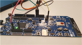
For a reason that I can't understand so far, I must erase the nRF52840 to be able to use UART1, TX RX on pins 0 1 (connector P14) to communicate with an external module.
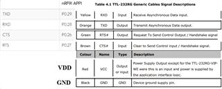
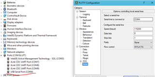
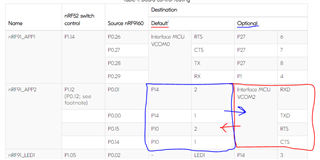
When nRF82840 is loaded with the default 9160 Board Controller FW, those pins are allocated to VCOM2.

This behavior is not in line with the datasheet statement : 5.7.1 nRF9160 DK board control

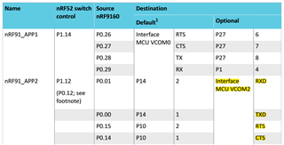
VCOM2 mapping is the optional config and must not be activated with the default nRF9160 Board Controller FW loaded in nRF52840.
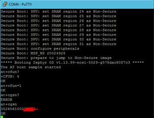
I tried again, erasing everything + reloading and all chars sent to UART1, TX pin, are displayed on my console VCOM2 rather than on my pin 1 connector P14.

Can someone explain why I have this behavior ?

  • Is there a way from nRF9160 FW to modify the nRF52840 behavior on those pins ? I might be doing something wrong....
  • I found the factory hex for nRF52840, where are located the corresponding sources for myself to rebuild it and eventually change the behavior ?

Thanks

Parents
  • Hi Nico,

    The different options that you can change in the board controller can be seen in the Kconfig file to the nrf52840_pca10090.


    So we need to build and flash a new application on the nrf52840 to route the pins.

    If you want to route the UART0 from VCOM0 (default) to the external pins (P0.26 - P0.29) we need to reflash the Board Controller (nrf52840) so it routes the pins differently.

    This can be done by just adding the following:

    CONFIG_BOARD_PCA10090_UART0_ARDUINO=y

    in the prj.conf file in for example the hello_world sample and build it for the nrf52840_pca10090 board.


    The same goes for when you want to route UART1 to the external pins (P0.01, P0.00, P0.15 and P0.14)

    Add the following:

    CONFIG_BOARD_PCA10090_UART1_ARDUINO=y

    in the prj.conf file.


    Adding a precompiled board controller application for routing out UART1 to the external pins:

    board_controller_uart1.hex
    Flash with command linenrfjprog --program boardcontroller_uart1.hex -f nrf52 --sectorerase -r --verify

    When flashing the nrf52840 remember to have the SW5 to nrf52.


    Example with interfacing with UART0:


    Here you can see how I connected the TTL-232RG-VIP-WE with the nrf91DK with UART0:

    So here I am running at_client sample on the nrf91 and use the UART from the TTL to send/receive AT-Commands:


    Best Regards,

    Martin L.

Reply
  • Hi Nico,

    The different options that you can change in the board controller can be seen in the Kconfig file to the nrf52840_pca10090.


    So we need to build and flash a new application on the nrf52840 to route the pins.

    If you want to route the UART0 from VCOM0 (default) to the external pins (P0.26 - P0.29) we need to reflash the Board Controller (nrf52840) so it routes the pins differently.

    This can be done by just adding the following:

    CONFIG_BOARD_PCA10090_UART0_ARDUINO=y

    in the prj.conf file in for example the hello_world sample and build it for the nrf52840_pca10090 board.


    The same goes for when you want to route UART1 to the external pins (P0.01, P0.00, P0.15 and P0.14)

    Add the following:

    CONFIG_BOARD_PCA10090_UART1_ARDUINO=y

    in the prj.conf file.


    Adding a precompiled board controller application for routing out UART1 to the external pins:

    board_controller_uart1.hex
    Flash with command linenrfjprog --program boardcontroller_uart1.hex -f nrf52 --sectorerase -r --verify

    When flashing the nrf52840 remember to have the SW5 to nrf52.


    Example with interfacing with UART0:


    Here you can see how I connected the TTL-232RG-VIP-WE with the nrf91DK with UART0:

    So here I am running at_client sample on the nrf91 and use the UART from the TTL to send/receive AT-Commands:


    Best Regards,

    Martin L.

Children
Related